Saturday, 19 April 2025

8th Bass Strait Voyage

 8th Bass Strait Voyage 

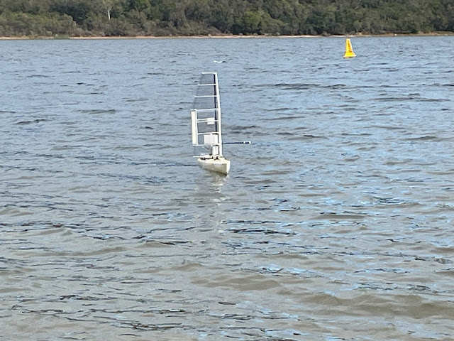
Just after dawn on April 13, 2025 suitable weather conditions lead to launching Voyager 2.8 from Flinders, Victoria. The intended destination was Torquay, but rougher than expected conditions later that cut the journey short.

Launch at Flinders Beach, after dawn.


Voyager departed Western Port Bay well pushing against a flooding tide, with Northerly wind of around 10 knots building to over 20 knots.


Voyager successfully exited Western Port Bay into Bass Strait, with northerly wind building to 20 knots.

Wing Sail damaged several miles out, approaching Cape Schanck waypoint.


Recovery from the rocks near Cape Schanck several days later.

Voyager lost control and drifted on the rocks during the next day, and was recovered two days after that.

She suffered a lot of damage on the rocks. The vent/antenna tube was broken off and the equipment housing filled with seawater, destroying the electronics. 
But the SD Card was still good !!

Analysis of the logs on the SD Card provided hints about what happened at sea.

It appears that the rough conditions with over 20 knots of wind combined with tidal movement caused breaking waves that tumbled the vessel, and damaged the tail on the wing sail.
It appears that the vessel lost drive from the sail, most likely due to the tail being damaged.

This is the second time the vessel has come ashore in Bass Strait due to suspected sail damage.

The logs showed that all of the electronics continued to function until a few hours after coming ashore on the rocks.


Conclusions

Its time to change the Wing Sail construction. Printed ABS components, with PVC film covering is ok in protected waters like lakes or Port Phillip.
But it is not suitable for Bass Strait.

Next Steps

My plan now is to develop new Wing Sail design and use new construction methods.
  1. I've always used NACA0018 foils. I plan to test designs using Eppler 169 foils due to their improved behaviour with the low Reynolds numbers encountered with small sailing drones. (calculated based on 12 knots of wind, over a chord length to 300mm to 450mm)
  2. The Tail assembly is fragile. I plan to develop a design where the tail is removed and the trim tab is included within the trailing edge of the wing sail to improve the robustness of the assembly.
  3. Effectively eliminating the tail will require the pivot point of the sail to move forward. A typical symmetrical foil is balanced about a point approximately 25% of chord from leading edge. 
    When a separate tail is added it ensures the  assembly will "weather cock".
    Without a tail, it will be necessary to move the pivot forward to ensure the wing sail continues to "weather cock". 
    I plan on commencing with 20% of the chord as the pivot point.
  4.  Initially development of the new sail design will be done using the same 3D printed ABS components with PVC film. This allows for rapid construction and is suitable for lake testing.
    The plan is that next time Voyager sails in Bass Strait the wing sail will constructed using foam core covered with fibre glass for increased strength. This is similar to the construction of the hulls, which has been very successful.
    I use 2 ounce fibre glass fabric with West System epoxy resin, over high density construction foam.


Magnetic Coupling for Steering V3

 Magnetic Coupling for Steering - V3

The magnetic coupling used to transmit the steering servo's torque to the rudder through a waterproof barrier has been quite successful.
But the design has evolved over the years, and it is time revisit the topic to explain the latest design.
I had previously used an array of a 8 magnets, 10mm x 3mm, per disk.

Magnetic Coupling Version 2 - new Magnet Layout


This worked fine on the smaller 1.2m vessel, but the larger 1.8m Voyager 3 was experiencing steering interruptions when the magnetic coupling would be overcome, and break free.
More torque was required in the magnetic coupling for the larger vessel.

Review of the V2 magnetic coupler

These images show the version 2 coupler that was used extensively on the smaller 1.2m sailing drone. 
When used on the larger 1.8m sailing drone, Voyager 3, it proved to provide inadequate torque.

When the relative torque was measured using a spring scale, it broke free at around 200g.

Version 2 Magnetic Coupler - 8 magnets 56mm diameter - magnet side.


Version 2 Magnetic Coupler - 8 magnets - other side.


V2 Magnetic Coupler - 12 Magnet

To increase the torque that could be transmitted by the coupler I tried adding an additional set of magnets, totalling 12 magnets per disk, and increased diameter of 76mm.

This worked ok, but in practice the increased diameter of the disk was going to require more clear space in the equipment bay, which would require shifting other components, and became too difficult.

When the relative torque was measured using a spring scale, it broke free at around 320g.

Version 2 Magnetic Coupler - 12 magnets 76mm diameter - magnet side

Version 2 Magnetic Coupler - 12 magnets - other side.

V3 Magnetic Coupler - 2 Magnets 

The next step was to employ larger magnets, 20mm x 4mm, on the same size disk of 56mm diameter.
This configuration yielded a significant increase in the torque that could be transmitted, within the same space. 

When the relative torque was measured using a spring scale, it broke free at around 525g.

This increase in performance yielded a practical result for the Voyager 3.
I have now retrofitted the smaller Voyager 2 with the same design of Magnetic Coupler. 


Version 3 Magnetic Coupler - 2 magnets 56mm diameter - magnet side


Version 3 Magnetic Coupler - 2 magnets - other side


View of 2-Magnet Coupler in the Voyager 3 Equipment Housing


View of 2-Magnet Coupler in the Voyager 3 Equipment Housing


View of 2-Magnet Coupler in the Voyager 3 Equipment Housing


The new coupler design has proven so good, it has been retrofitted the smaller Voyager 2.

View of 2-Magnet Coupler retrofitted to Voyager 2, shown partially installed


Compass Interference

Of course stronger magnetic fields on a small sailing drone create problems for the magnetic compass.
The only solution is to increase physical separation until the magnetic interference with the compass reduces to a tolerable level.

The following images shows a simple test set up to observe the effects of the new Magnetic Coupler on the magnet compass located within the equipment housing.

It showed the interference dropped to reasonable levels once separation was increased by around 100mm to 200mm.

Testing for Compass Interference


 This was handled in Voyager 3 by adding an additional compass on the deck well forward of the equipment housing, but not too close to the magnetic disk used for the wing angle measurement, as shown in the following image:


New compass mounted away from magnets to reduce interference.


Wednesday, 22 January 2025

Market Review of Small Brushless Servos

Market Review of Small Brushless Servos

Servos employing brushless motors won't fail from a brush failure. 
So servos with brushless motors should be inherently be more reliable and last longer than servos with brushed motors.

Brushless servos tend to be larger high-torque servos when compared with servos with brushed motors.
They also tend to be completely digital devices and in most cases may be programmed to change some of their attributes, using simple USB programmers.
I sourced five different brushless servos from China to review and test. They were all the smallest brushless servos available in their range. They were all standard sized servos, with approximate dimensions of 40mm long and 20mm wide.

The desirable characteristics of a steering servo for a small long duration sailing drone:
  • low idle current
  • low operating current
  • high torque is not important
  • fast response is not important
The programmable servos could be altered to reduce their current draw, and hence reduce the torque they can apply. The primary attribute affecting torque and current draw is the maximum duty cycle.

My preferred servo at the time of writing is the Yipin X10.

Hitec HS-425BB - Brushed Servo - for comparison

Summary: This is a good standard brushed motor servo. Voyager sailing drones have sailed many miles with these servos and similar ones in the Hitec range.

Landed Price: AUD $25
Idle current:     9mA
Specified Torque: 4kg
Programmable: No
Spline:    24T
mass:    43g

Current measurements after optimum programming for reduce power consumption:
All testing performed at 5Vdc.
Idle current:     16mA
Step current:    1000mA
Sweep current: 100mA


9imod Brushless 20kg 

Summary: This is good value for money brushless motor servo.
It is only slightly more expensive than brushed motor servo.

Landed Price: AUD $33
Specified Torque: 20kg
Programmable: Yes
Spline:    25T
Mass:    72g
web:
GXservo-v1.rar - ServoDebugger.exe, older version of software, but does work on  my Windows machines.
GXservo-v3.rar - newer version, but crashes out on my Windows computers.

Current measurements after optimum programming for reduce power consumption with adequate torque of around 1kg.cm:
All testing performed at 5Vdc.
Idle current:     12mA
Step current:    360mA
Sweep current: 200mA


DS Power DS-B008-C  24kg

Summary: It sounds very smooth and quiet. Build quality is good.
But it not programmable, ands that means that it can't be optimised for a role.

Landed Price: AUD $49
Specified Torque: 24kg
Programmable: No
Spline:    25T
mass:    66g

Current measurements as supplied (programming is not an option):
All testing performed at 5Vdc.
Idle current:     40mA
Step current:    2000mA
Sweep current: 290mA


Yipin X10 

Summary: This is my favorite brushless servo.
Possibly the best quality servo of those surveyed. The Yipin Servo uses the same PCB as the 9imod servo, but the build quality seems to be better.
They both can be programmed using the same programmer and software.
The Yipin servo comes with spare gears and pins.

Landed Price: AUD $81
Specified Torque: 10kg
Programmable: Yes
Spline:    25T
mass:    72g
web:
GXservo-v1.rar - ServoDebugger.exe, older version of software, but does work on  my Windows machines.
GXservo-v3.rar - newer version, but crashes out on my Windows computers.

Current measurements after optimum programming for reduce power consumption with adequate torque of around 1kg.cm:
All testing performed at 5Vdc.
Idle current:     12mA
Step current:    450mA
Sweep current: 200mA


AGFC A73BHLW

Summary: This servo includes feedback in the form a 4th connection wire.
It is simply a direct connection to the potentiometer wiper pin. 
This could be done on almost any servo without cost.

Landed Price: AUD $165
Specified Torque: 40kg
Programmable: Yes
Spline:    25T
mass:    79g

Programming software:     AGF-SPV3 USB programming card
                                           https://agfrc.com/index.php?id=2581

Current measurements after optimum programming for reduce power consumption with adequate torque of around 1kg.cm:
All testing performed at 5Vdc.
Idle current:     34mA
Step current:    390mA
Sweep current: 90mA