Saturday, 19 April 2025

Magnetic Coupling for Steering V3

 Magnetic Coupling for Steering - V3

The magnetic coupling used to transmit the steering servo's torque to the rudder through a waterproof barrier has been quite successful.
But the design has evolved over the years, and it is time revisit the topic to explain the latest design.
I had previously used an array of a 8 magnets, 10mm x 3mm, per disk.

Magnetic Coupling Version 2 - new Magnet Layout


This worked fine on the smaller 1.2m vessel, but the larger 1.8m Voyager 3 was experiencing steering interruptions when the magnetic coupling would be overcome, and break free.
More torque was required in the magnetic coupling for the larger vessel.

Review of the V2 magnetic coupler

These images show the version 2 coupler that was used extensively on the smaller 1.2m sailing drone. 
When used on the larger 1.8m sailing drone, Voyager 3, it proved to provide inadequate torque.

When the relative torque was measured using a spring scale, it broke free at around 200g.

Version 2 Magnetic Coupler - 8 magnets 56mm diameter - magnet side.


Version 2 Magnetic Coupler - 8 magnets - other side.


V2 Magnetic Coupler - 12 Magnet

To increase the torque that could be transmitted by the coupler I tried adding an additional set of magnets, totalling 12 magnets per disk, and increased diameter of 76mm.

This worked ok, but in practice the increased diameter of the disk was going to require more clear space in the equipment bay, which would require shifting other components, and became too difficult.

When the relative torque was measured using a spring scale, it broke free at around 320g.

Version 2 Magnetic Coupler - 12 magnets 76mm diameter - magnet side

Version 2 Magnetic Coupler - 12 magnets - other side.

V3 Magnetic Coupler - 2 Magnets 

The next step was to employ larger magnets, 20mm x 4mm, on the same size disk of 56mm diameter.
This configuration yielded a significant increase in the torque that could be transmitted, within the same space. 

When the relative torque was measured using a spring scale, it broke free at around 525g.

This increase in performance yielded a practical result for the Voyager 3.
I have now retrofitted the smaller Voyager 2 with the same design of Magnetic Coupler. 


Version 3 Magnetic Coupler - 2 magnets 56mm diameter - magnet side


Version 3 Magnetic Coupler - 2 magnets - other side


View of 2-Magnet Coupler in the Voyager 3 Equipment Housing


View of 2-Magnet Coupler in the Voyager 3 Equipment Housing


View of 2-Magnet Coupler in the Voyager 3 Equipment Housing


The new coupler design has proven so good, it has been retrofitted the smaller Voyager 2.

View of 2-Magnet Coupler retrofitted to Voyager 2, shown partially installed


Compass Interference

Of course stronger magnetic fields on a small sailing drone create problems for the magnetic compass.
The only solution is to increase physical separation until the magnetic interference with the compass reduces to a tolerable level.

The following images shows a simple test set up to observe the effects of the new Magnetic Coupler on the magnet compass located within the equipment housing.

It showed the interference dropped to reasonable levels once separation was increased by around 100mm to 200mm.

Testing for Compass Interference


 This was handled in Voyager 3 by adding an additional compass on the deck well forward of the equipment housing, but not too close to the magnetic disk used for the wing angle measurement, as shown in the following image:


New compass mounted away from magnets to reduce interference.


Wednesday, 22 January 2025

Market Review of Small Brushless Servos

Market Review of Small Brushless Servos

Servos employing brushless motors won't fail from a brush failure. 
So servos with brushless motors should be inherently be more reliable and last longer than servos with brushed motors.

Brushless servos tend to be larger high-torque servos when compared with servos with brushed motors.
They also tend to be completely digital devices and in most cases may be programmed to change some of their attributes, using simple USB programmers.
I sourced five different brushless servos from China to review and test. They were all the smallest brushless servos available in their range. They were all standard sized servos, with approximate dimensions of 40mm long and 20mm wide.

The desirable characteristics of a steering servo for a small long duration sailing drone:
  • low idle current
  • low operating current
  • high torque is not important
  • fast response is not important
The programmable servos could be altered to reduce their current draw, and hence reduce the torque they can apply. The primary attribute affecting torque and current draw is the maximum duty cycle.

My preferred servo at the time of writing is the Yipin X10.

Hitec HS-425BB - Brushed Servo - for comparison

Summary: This is a good standard brushed motor servo. Voyager sailing drones have sailed many miles with these servos and similar ones in the Hitec range.

Landed Price: AUD $25
Idle current:     9mA
Specified Torque: 4kg
Programmable: No
Spline:    24T
mass:    43g

Current measurements after optimum programming for reduce power consumption:
All testing performed at 5Vdc.
Idle current:     16mA
Step current:    1000mA
Sweep current: 100mA


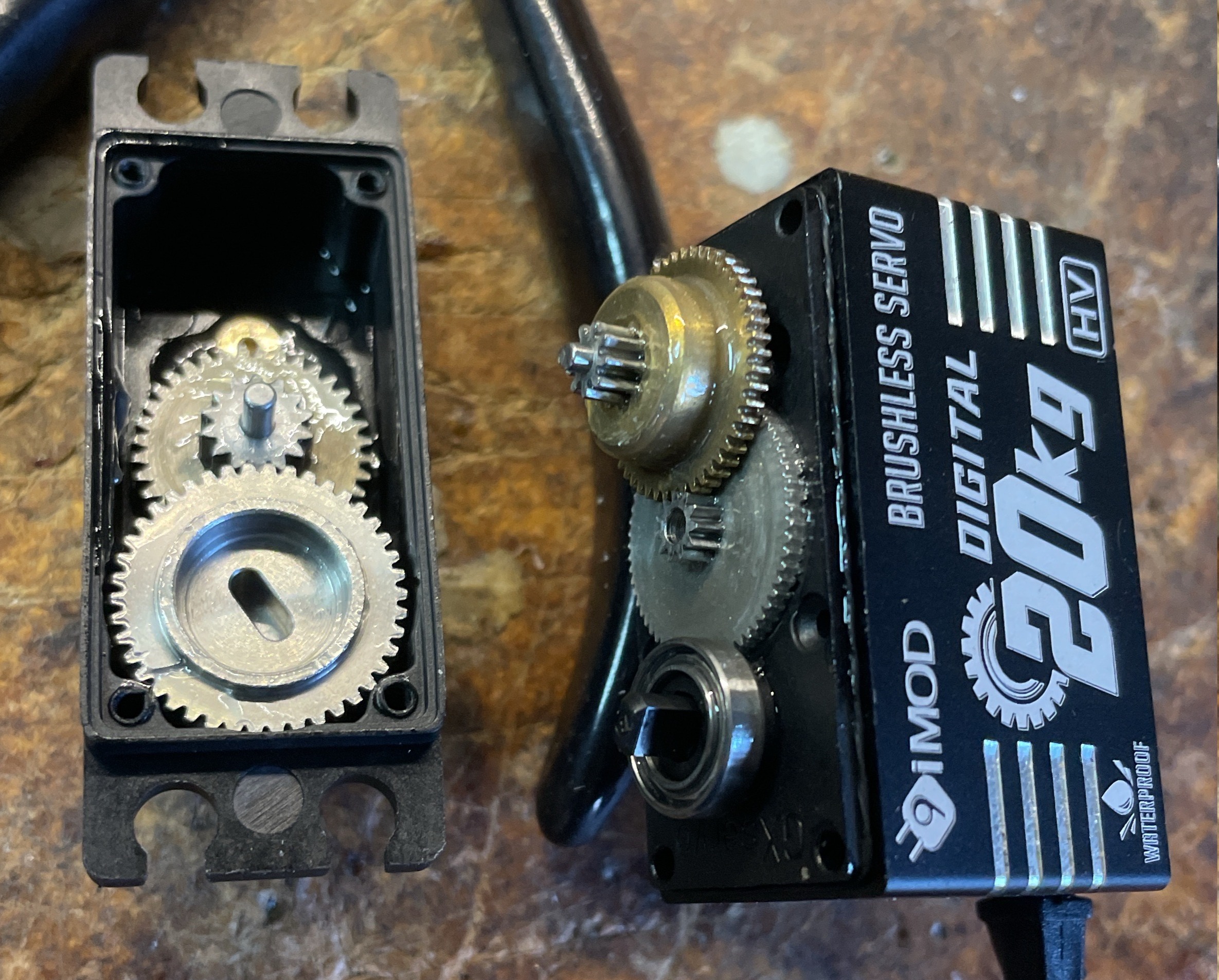
9imod Brushless 20kg 

Summary: This is good value for money brushless motor servo.
It is only slightly more expensive than brushed motor servo.

Landed Price: AUD $33
Specified Torque: 20kg
Programmable: Yes
Spline:    25T
Mass:    72g
web:
GXservo-v1.rar - ServoDebugger.exe, older version of software, but does work on  my Windows machines.
GXservo-v3.rar - newer version, but crashes out on my Windows computers.

Current measurements after optimum programming for reduce power consumption with adequate torque of around 1kg.cm:
All testing performed at 5Vdc.
Idle current:     12mA
Step current:    360mA
Sweep current: 200mA


DS Power DS-B008-C  24kg

Summary: It sounds very smooth and quiet. Build quality is good.
But it not programmable, ands that means that it can't be optimised for a role.

Landed Price: AUD $49
Specified Torque: 24kg
Programmable: No
Spline:    25T
mass:    66g

Current measurements as supplied (programming is not an option):
All testing performed at 5Vdc.
Idle current:     40mA
Step current:    2000mA
Sweep current: 290mA


Yipin X10 

Summary: This is my favorite brushless servo.
Possibly the best quality servo of those surveyed. The Yipin Servo uses the same PCB as the 9imod servo, but the build quality seems to be better.
They both can be programmed using the same programmer and software.
The Yipin servo comes with spare gears and pins.

Landed Price: AUD $81
Specified Torque: 10kg
Programmable: Yes
Spline:    25T
mass:    72g
web:
GXservo-v1.rar - ServoDebugger.exe, older version of software, but does work on  my Windows machines.
GXservo-v3.rar - newer version, but crashes out on my Windows computers.

Current measurements after optimum programming for reduce power consumption with adequate torque of around 1kg.cm:
All testing performed at 5Vdc.
Idle current:     12mA
Step current:    450mA
Sweep current: 200mA


AGFC A73BHLW

Summary: This servo includes feedback in the form a 4th connection wire.
It is simply a direct connection to the potentiometer wiper pin. 
This could be done on almost any servo without cost.

Landed Price: AUD $165
Specified Torque: 40kg
Programmable: Yes
Spline:    25T
mass:    79g

Programming software:     AGF-SPV3 USB programming card
                                           https://agfrc.com/index.php?id=2581

Current measurements after optimum programming for reduce power consumption with adequate torque of around 1kg.cm:
All testing performed at 5Vdc.
Idle current:     34mA
Step current:    390mA
Sweep current: 90mA


Sunday, 22 September 2024

Servo Endurance and Failure

 Servo Endurance and Failure


The main steering servo that has been used in Voyager 2 has been the Hitec HS-322HD.
Several of these servos have been used in the life of the Voyager 2.
The original steering servo used in lake conditions, from 2016 was being retired in late 2019, prior to commencing ocean voyages, and stored away for possible use in less critical projects.


Hitec HS-322HD


A few years later in January 2023 this servo tested for its endurance by exercising without load until it failed.
It completed around 4 million movements before failure.

The failure occurred in the brushes of the DC motor .

The image below shows two motors from HS-322HD servos where the brushes had failed.
In both cases the filed brushes lead to a failure of FET drivers in the H-Bridge.
The brush housing on the left is from the motor tested to failure without load, to 4 million operations.
The one on the right failed at sea, leading to the stranding of the Voyager near Cape Schank in April 2024.


Failed DC Motor Brushes


Servo Driver board showing burnt-out FET drivers.


The steering servo on board Voyager for the 6th voyage in Bass Strait, failed in April 2024.
It failed after an estimated 280,000 operations. This is well short of the anticipated 4 million operations from the previous no load endurance testing.

The plan moving forward is to investigate the availability and suitability of servos that utilize brushless motors.

The Hitec HS-322HD has a torque rating of 3kg at 1cm.
The smallest brushless servo seems be rated at 10kg at 1cm.


Saturday, 21 September 2024

100 days on a Beach - 6th Bass Strait Voyage

100 days on a Beach and a broken leg - 6th Bass Strait Voyage 

The 6th voyage on Bass strait for Voyager 2.7, commenced from Torquay Fishermen's Beach at around 4:45pm April 17th  2024.
Conditions were good.

Pre-launch at Torquay Fishermen's Beach 


But, the next day after around 28 hours sailing, Voyager appeared to suddenly deviate from course and drift to coast under the influence of the South-Westerly  wind, and eventually washed up in an isolated cove near Cape Schank, Victoria.

Track reported by the Satellite tracking showing the apparent time of failure.


The coast near Cape Schank is difficult to access so recovery will be difficult.
The coast line is mostly cliffs around 30metres high. It is mostly private rural residential land or farm land.

I attempted to gain access by following a gully down to the coast, but during the hike, I fell and broke my leg. This put me out of action for around 10 weeks.


Coast near Cape Schanck where Voyage come ashore.


The Satellite locator beacon continued to function for several weeks until the batteries finally ran down. the last signal was received at 9pm 22/5/2024, after 35 days. 

While recovering from my broken leg, I formed plans to recover Voyager by water, using my kayak.
The nearest practical location to commence the recovery trip was from Flinders Ocean Beach. This beach had easy access by car, and is protected by offshore reefs.
This would result in a journey 4 miles WSW toward Cape Schank, to the location of  Voyager.


Planned recovery journey in a kayak from Flinders Ocean Beach.


Then on 6th July 2024, after 80 days, a friend flew his light aircraft over the location of Voyager, took photographs, that showed the boat was still in the cove.
It is visible in the image below as the white dot on the beach above the high water mark.


View of Voyager from the air.


I planned my recovery trip using the kayak. I practiced paddling an equivalent distance in the Yarra River near to home to ensure that I could complete the journey in Bass Strait.
I needed calm conditions in Bass Strait, with out too much wind or swell, and not too much rain.
I made two trips to launch location, 1.5 hours drive away, but did not proceed because I was not happy about the conditions. 
The third time the conditions were good to proceed, and on 30th July 2024 at around 10am I started paddling.
The trip in the kayak was around 2 hours, and timed for low tide at the destination.

Voyager was found high up on the pebble beach as expected.
The beach consisted of wave washed rocks around 6 inches across. it was difficult to walk on.

Voyager was found in good condition, considering it had been on the rocky beach for over 100 days by now.
The electronic housing was intact, and the electronics were in good condition.
 

She had been on the beach for 100 days, or 3 1/2 months.


Voyager 2.7 as found after 100 days


Voyager was strapped on to the kayak, and I headed home as quickly as possible, retracing the 4 miles back to Flinders Ocean Beach, another 2 hours.


After recovery, heading home.


What caused the failure ?

At first I thought the failure was due to a mechanical problem with the Wing Sail. 
The Tail section was completely missing, including the stainless steel screws, leaving clean 2mm threaded holes in the carbon fibre tail booms.

The electronics appeared to be in good. 
I powered up the electronics while preparing to rebuild and relaunch Voyager.
But I was surprised to find the main steering servo was not operating, despite appearing to be in good condition.

The servo was disassembled and revealed an obviously burnt-out FET driver transistor.
This is one of the four FET driver transistors that form the H-bridge DC motor driver.

Steering Servo showing the burnt FET Motor Driver.


Further disassembly revealed that the brushes on the DC servo motor had failed.
The brushes each consist of around 4 fingers of brass or bronze.
The image below shows one of the fingers has been displaced and was on the wrong side of the commutator.
This would have shorted-out the motor causing the failure of the FET driver transistor.


Servo Motor with failed brush


I had previously studied the log files on the SD Card, but had not looked carefully at the current consumption.

After reviewing the current consumption, the time of failure of the servo become clear, and is shown in the image below.
the servo failed at around 80,000 seconds into the voyage, or around 22 hours.

Plot of Current versus time showing failure near 80,000seconds.


The failure time was reviewed against the track taken by Voyager, and is shown in the image below.
More detailed review of the logs around this time showed, the vessel lost steerage and its heading appeared uncontrolled from the time onwards. 
It was quite a coincidence that the wind was running almost directly down the desired course.
This continued for around 4 hours, until the wind changed direction and blew the vessel toward land.


Actual steering servo failure time 


The servo had failed prematurely. 
It was a Hitec HS-322HD.
Previous servo endurance testing had yielded around 4 million operations before failure, due to the failure of  the motor brushes.
This servo failed at around 280,000 operations. well below expectations.
Typical servo usage seems to be around 50,000 movements per day.

Servos will be covered in more detail in a future article.
The plan is to investigate brushless servos that should have a much greater lifespan.

Sunday, 7 April 2024

Salt water and Electronics - 5th Bass Strait Voyage

 Salt Water and Electronics - 5th Bass Strait Voyage

After quickly recovering from the prior launch and recovery on Friday 22/3/2024, the vessel was ready for another launch 11 days later on Thursday 2/4/2024, the 5th voyage on Bass Strait.

Following the prior launch and recovery on the Friday, the compass had been replaced and recalibrated yielding much better accuracy. The aim was specifically to improve the determination of the True wind Direction, which contributed to the failure as discussed in the last post.
Om that Friday night, the vessel had been recovered high and dry on the beach after it had been washed ashore, through the small surf.
There was little damage, but the sail and its electronics would have been submerged in the breaking waves on beach.

It was considered that there were no electronic problems with the Sail, and so the vessel was launched again on Thursday 2/4/2024.

Launch from Torquay 2/4/2024 at 8:15pm, soon after sunset


It sailed well, in the light to moderate conditions for the next 16 hours, and almost 15 miles down the course, at which point it failed to proceed down the course, and to started to drift back toward the launch place.
The conditions at that point were very calm.


The vessel drifted back to the west for 2 days and returned coincidentally almost back to the launch point. 

As the boat approached the shore it was possible to interrogate it using the LORA telemetry, when it was within around 2km of the headland.
It was possible to confirm that most of the components were operational.
However the wing sail had not responded to regular polling, since the time of failure, 2 days earlier.
This implied that the Wing Sail controller had failed.

The vessel was safely brought to shore by swimming out to retrieve it, to avoid it entering the breakers. 


Safely retrieved, and brought to shore before entering the breakers.


It was noted that wing sail servo was not operational, and was in the neutral position.
This suggests that it is likely that the last action performed by the controller was to partially reboot, and center the servo. If it had failed without involving a reboot, the servo would most likely have been set to one side or the other.

The electronics were switched off, and then switched back on again, and the Wing Sail returned to operation.

Later inspection of the Wing Sail controller revealed evidence of corrosion, despite the epoxy coating.
It appears that the epoxy coating was incomplete, and allowed salt water to come in contact with the electronic components.
It is believed that this was the reason for the failure of the Wing Sail controller.

It seems likely that the voyage 11 days earlier, where the Wing Sail would have been submerged in the sea water may have allowed salt to remain in voids or fissures in the epoxy coating.
Whilst dry, the salt would not have had any effect.
 
It seems likely that on the next voyage, the moist atmosphere would allow the salt to affect the circuitry.

Wing Sail Controller showing corrosion - top view

Wing Sail Controller showing corrosion - side view


To address this problem, the Wing Sail controller will be fully potted in epoxy.
A new PCB mount, incorporating a potting box has been 3D printed.


New Wing Sail Controller, located in 3D printed potting box


Monday, 1 April 2024

The Importance of True Wind Direction for a Sailing Drone

 The Importance of True Wind Direction for a Sailing Drone - 4th Bass Strait Voyage

An opportunity arose on the evening of 22/3/2024 to commence a passage in Bass Strait from Torquay to Western Port. An 80km (50 mile) passage that would be expected to take around 48 hours.
The mission failed within a couple of hours, with the vessel running ashore before midnight of the same evening.


Torquay Fishing Beach 7pm launch


Conditions were calm as the vessel ran downwind to the lee shore.
The vessel was found with minor damage on the beach.
The first question was whether the damage occurred at sea and caused the failure of the mission, or whether the damage occurred when the vessel was beached.

The equipment housing was completely intact and the equipment was fully operational.
Later analysis of the log files contained on the SD Card showed that the failure was due to the sailing algorithms making bad decisions.


Midnight on the beach


Spot GPS Satellite position reports


The sailing algorithm aims to get the vessel to the next waypoint, while remaining within a maximum permissible cross track error (CTE) from the rhumb line. 
It does this by trying to sail the course, using the favoured tack.
If it can't make the waypoint directly, it will sailing until the CTE reaches the Maximum CTE (boundary) permitted for the current waypoint and then change tack.
If it is unable to directly sail for the next waypoint, it is assessing at all times whether it is able to reach the next waypoint directly on the other tack.

The determination of whether it is possible to sail directly to the waypoint on the other tack is a key issue.

Analysis of the logs showed the following:
  • The vessel could not quite sail directly to waypoint.
  • It gradually reached CTE Max on the leeward side of the course (port side of course) on starboard tack.
  • Having reached the boundary, it gybed on to port tack.
  • Then it reassessed the course to the waypoint  (if it were to change starboard tack) and decided it was directly sailable.
  • So, it gybed back on to starboard tack again, but it wasn't directly sailable, and it was still beyond Max CTE.
  • The process repeated.
  • The effect was to gybe and gybe again. effectively running downwind, until it beached on the lee shore.


Position Log from SD Card


The key issue was the wrong assessment of whether the waypoint could be directly reached on the other tack.
When racing sailing a full size yacht it can be tricky to assess when to tack to make the next mark without overlaying or underlaying.

The algorithm for assessing whether the waypoint can be reached directly on the other tack is as follows:
  • Compare the Bearing to Waypoint (BTW) with the True Wind Direction (TWD) less the minimum sailing angle from the wind, less an additional sailing margin.
  • The sailing margin is currently set to 25 degrees. This is effectively a measure of how much to overlay the mark before considering it is sailable.

Correctly estimating the TWD is critical for making correct decisions, and this was the source of the problem.

The determination of TWD is performed approximately as follows:
  • True heading of vessel (HDG_T),
  • less Apparent Wind Angle (AWA) 
  • less correction adjustments to include an approximation for boat speed..
So the main requirements for determining TWD is to measure an accurate vessel heading, and apparent wind angle.

The main problem with Voyager 2.7 was the accuracy of the magnetic heading.


The following plot illustrates the relationship between the vessel heading and the calculated AWD, as it was during the failed mission.
The plot was prepared from data recorded on the SD Card, while the vessel was rotated on a turntable to assist gathering measurements.

It shows that the AWD varied by up to 47 degrees with different headings.

AWD versus Heading as it was for the mission


The compass was upgraded by removing the UFSF Max IMU , and replacing it with the LSM303.
The improvements brought by the new compass, and careful calibration, and minor adjustments to the calculations greatly improved the results.

The resulting plot of AWD versus Heading after the upgrades performed, yielded significant improvements, as seen by the near flat orange line.

The variation of AWD was less the 6 degrees with heading completing three full turns.


AWD versus Heading after upgrades


Then end result should yield a much more accurate AWD and hence estimated TWD.
The next ocean voyage should be telling.