Wednesday, 6 January 2021

Another Port Phillip Crossing Attempt - Post COVID Lockdown

Another Port Phillip Crossing Attempt - Post COVID Lockdown

Melbourne, Australia has come out of the second lockdown recently, so on December 10 2020, I commenced another run across Port Phillip.
In the months since the last run we've been in lock down for weeks at a time and not permitted to either leave home or leave our local area without good reason.
During this time Voyager 2.0 has had some hardware and software updates based on lessons learnt during the last crossing attempt.
The main software issue being addressed was the method of correcting the course as the vessel is steering toward a distant waypoint.


Checks done. Ready to go again.

 Steering to a Waypoint

When waypoints are only a few hundred metres away, it is simple to steer a course representing the Bearing to Waypoint (BTW) and you will typically arrive there, having followed closely along the rhumb line.

When the waypoint is many miles away, and the steering method is to steer the BTW, then it is quite likely that the vessel will deviate great distances from the rhumb line over a period of time.

This was one of the problems encountered during the last voyage across Port Phillip in March 2020.

The main software design change since then was to continual measure the Cross Track Error  (CTE) and use this to add a proportional course correction to the BTW to encourage the vessel to return to the rhumb line. The amount of course correction to apply is calculated as the ratio of CTE to CTEMax (where CTEMax is defined in the mission as half width of the corridor to the next waypoint), multiplied by gain constant.

Hence the simple course to be steered is: BTW - CTE/CTEMax x Kc

Note: This is all assuming that a course can be laid directly to the waypoint without tacking. If tacking is required, then a whole set of different rules apply which are beyond the scope of this article.

The first 10 hours were good

The vessel sailed from east to west, and for the first 10 hours was perfectly on course, staying very close to the rhumb line.

Unfortunately, at 6am the next morning, it was once again picked up be a fishing boat. A commercial fishing vessel this time.
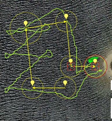
This can be seen in satellite tracking plots shown in the image below. It was picked up in the middle of Port Phillip, as it was heading eastward, and carried on the remainder of their fishing trip, before the fishing vessel returned to her home port of Port Arlington.  I arranged to meet them there for the handover.

Satellite Tracking Plot 


Mission in Yellow and actual course in Green. You can hardly separate them

Conclusions

The new method of steering using CTE combined with BTW appears to work well.

I've tried to sail across Port Phillip twice now, and failed both times due to human intervention.

I'll need to add signage suggesting to "KEEP CLEAR" or head out to the open ocean where there's less chance of meeting other vessels.

Port Arlington - Home Port for the last vessel to "rescue" Voyager

This is part of the ongoing development of a low cost autonomous oceangoing sailing drones, utilising a self-trimming wingsail. This is the Voyager series of sailing drones.

Saturday, 22 August 2020

Solar Charging Trials during COVID19

Solar Charging Trials - in COVID Times.

It is August 2020 in Melbourne, Australia. We haven't been allowed to travel any distance for many weeks now, so there's no sailing trials permitted for hobbyists. So no chance to test the new sail, or the new LoRa telemetry system now installed on Voyager 2.0.

This allows time to start looking ahead to Voyager 3.0, which will be a scaled up version of Voyager 2.0 at 2m LOA, and about 0.5m in beam.

The intention of Voyager 3.0 is that it has a large enough deck space to accommodate enough solar cells to allow for missions of indefinite duration. Currently the battery capacity of Voyager 2.0 is about 80 to 120 hours (4 or 5 days). The Wingsail battery life is about 200 hours (8 days).

The Solar Cells in use are the Sunpower C60 cells. These are a light weight and flexible (within limits) and can be sliced up. They can provide over 3A at around 0.5V in direct sun. I'm currently slicing them into thirds, which can yield around 1A at 0.5V per cell in direct sun, and of course when connected in series, the three cells can yield 1.5V at 0.5A.

The image below shows a typically test set up for working out the basic parameters of the charging setup.

Preliminary Test Set up for assessing Cell Quantity and Charging Circuits

In order to evaluate different Solar Charging arrangements in the real world, I commenced with the Wingsail by pressing into service the failed (overweight) WingSail #2. This was kitted out with 4 third size slices of Sunpower C60 Cells in conjunction with the LTC3015 Step up DC-DC converter charging a single 18650 Li-ion cell. The load is the current Wingsail Controller board, but without the Bluetooth module, which was replaced with an Ebyte LoRa module instead. The Wingsail Controller was programmed with software primarily intended to read 3 sets of Voltages and currents and transmit them to a monitoring station.


Mock up of the Voyager Wingsail and electronics for trialing Solar Charging

It will be necessary to place cells on both sides of the sail.
The current Wingsail (without Solar Charging) has two 18650 cells. It is expected that only one cell will be required once solar charging is used. This will partially offset the increased weight due to solar cells (but not by much).

The test rig charging circuits and the the test rig software  are still being adjusted, but the aim is to monitor the operation of the solar charged Wingsail over a period of a month or so.
During this time, we'll start on a mock up of the deck of  the future Voyager 3.0 and set up a solar charging test rig for her.

This is part of the ongoing development of a low cost autonomous oceangoing sailing drones, utilising a self-trimming wingsail. This is the Voyager series of sailing drones.


Sunday, 21 June 2020

Change Over to LoRa for Telemetry

Change Over to LoRa Radio for Telemetry

The Telemetry Radio used onboard Voyager 2.0 for the past few years has been the standard 433Mhz APM Telemetry Radio.

It operates well over short distances of a few hundred metres, as a transparent full duplex serial link, with a default transmission rate of 57600 Baud.

Traditional APM Telemetry Radio


The design of the telemetry system was that the vessel would constantly broadcast telemetry messages, whether they were being received or not.
The specific messages being broadcast are enabled by bit mask.
The mission definition does support power control where the telemetry radio can be powered off or on during specific mission steps.
The problem with the standard low cost telemetry radio is that distance is very limited. More efficient antennas were used to extend the range to a few hundred metres, but the link was always marginal at that distance.

LoRa Radio
LoRa (Long Range) Radio offers long range communications up to several kilometers with line of sight. 
LoRa is proprietary technology developed by Semtech, who provide a range of transceiver chips, primarily the SX1278. Many PCB modules are available from multiple suppliers using the SX1278 device.
The module used here is the Ebyte 433MHz E32-433T20DT 100mW.

Ebyte 433MHz LoRa Radio


The Ebyte module incorporates additional microprocessing components in order to provide a serial interface, making it reasonably simple to incorporate into the existing Voyager Controller design.


Ebyte Modules mounted for use with USB for the Voyager Base Station and a Serial Connection for use onboard.

The Ebyte LoRa module uses an effective transmission rate of approximately 2400 Baud. It can be increased, but that is at the cost of reduced range. The default rates are being used here.

The design of the telemetry system has been changed to a "request" system, rather than a broadcast system. This means that the vessel remains mostly silent and only transmits telemetry messages in response to specific requests from the Voyager Base Station.
Hence the scheduling of telemetry messages is dictated by the Base Station.

This alleviates the need to consider power control for the Telemetry Radio on board the vessel, because it will only transmit on demand.

The main aim of changing to LoRa Radio is to gain increased range for telemetry and control of the vessel. This should allow faster reconfiguration and testing of the Wingsail and the vessel, without the need to keep returning to shore.


Note: This is part of the ongoing development of a low cost autonomous oceangoing sailing drones, utilising a self-trimming wingsail. This is the Voyager series of sailing drones.

Wingsail Development

Wingsail Development 

All sailing testing so far has been performed using the one sail. It was originally designed and made as a very conservative prototype, not trying to push the boundaries far.
Its been a tough and reliable sail, with its longest voyage being across Port Phillip over a couple of days.

Wingsail #1

Dimensions:

  • Height 1000mm
  • Chord Length 150mm
  • Area 0.15 sq metres
  • NACA 0015 (15% Chord)
  • Weight 820g

Wingsail #1


Wingsail #2

This Wingsail was short lived. Not enough thought was put into its weight and the stability of the boat. I thought the stability margin was quite high and didn't need to be considered much.
That was very wrong !

Dimensions:

  • Height 1100mm
  • Chord Length 330mm max, tapering down to 165mm.
  • Area 0.32 sq metres
  • NACA 0018 (18% Chord)
  • Weight 1298g


Wingsail #2 - too heavy

When Wingsail #2 was trialed in the water in a mild 10 knot wind, the boat simply laid over and wouldn't right itself. A big failure.

Stability Measurements

It was clearly important to stop assuming the stability margin would be ok, and actually take measurements.

A setup was established to measure the mast tip loading required to hold the boat flat at 90 degrees of heel.

With Wingsail#1, the mast tip loading was measured at 475g at a distance of 1210mm from the deck.
This sail has demonstrated good performance in strong winds.

With Wingsail#2, the mast tip loading was only 250g at the same height off the deck, and boat laid over in mild wind.


Wingsail #3

Wingsail #3 is the same size as Wingsail #2, but it has been designed to minimize weight and heeling moment while retaining as much strength as possible.

Dimensions:

  • Height 1100mm
  • Chord Length 330mm max, tapering down to 165mm.
  • Area 0.32 sq metres
  • NACA 0018 (18% Chord)
  • Weight 980g

Changes:

  • The printed components were all redesigned to reduce weight. Previously, the printed pieces were designed as mostly solid pieces, and printed with infill of about 10% to reduce weight, as well as incorporating large circular holes. The components were all redesign by shelling them to about 1.5mm.
    Continuous checks were made on the design of each component by performing the slicing operation and noting the length of filament that would be consumed, in order to estimate the weight of the finished item.
    The weight of the finished component was determined to be 7g per metre of filament, as reported by the slicer.
    The end result was a reduction of mass of the printed components by almost 50%.
  • The film previously used was 250 micron A4 sized clear acetate film, used for binding documents. I'm now using 200 micron A3 sized film.
    This has plenty of stiffness for a sail of this size, and the larger A3 size allows for less overlapping seems, and hence a neater result with reduced weight.
  • Lower the centre of mass.
    The electronics and the battery with its switch, were lifted on Wingsail#2 in an effort to ensure it was high out of the water. This was a mistake because of the significant cost in loss of stability.
    The battery and electronics are now as low as possible, while remaining forward of the mast.
  • Lower the centre of mass.
    The tail section and the forward counterweight have been dropped by 200mm, so that they are as low on the deck as practical.
    This has a significant effect on stability.
  • The 12mm aluminium mast has been replaced with carbon fibre.
    The carbon fibre mast now consists of  three sections:
    • 500mm by 12mm OD and 10mm ID
    • 500mm by 10mm OD and  8mm ID
    • 1000mm by 8mm OD and 6mm ID
  • The Carbon Fibre tubing fits nicely together as a press-fit, to form a tapered mast.
    The aluminium mast weighed 125g. The carbon fibre tapered mast weighed 76g.

Result

The new Wingsail #3 has a mass of 980g (roughly 320g less than #2).
It requires a tip loading of 500g to hold the boat flat a 90 degrees of heel. This is a great improvement, and is slightly higher than 475g of Wingsail #1.


Wingsail #3

Next Steps

The next step is to get the boat in the water for trials.
There is still room for improvement in reducing the heeling moment due to mass, by reducing the mass of the tail. This causes a second-order problem, because the counter-weight is unnecessarily large to balance the tail. Hence, any improvement in the weight of the tail should see almost a double improvement in overall weight.

Tuesday, 26 May 2020

Resolutions from the First Long Voyage - March 2020

This post covers each of the issues identified after the March 2020 Voyage across Port Phillip, and the resolution.

Cross Track Error Resolution

The Cross Track Error (CTE) calculation has poor resolution when the waypoint is many miles away (e.g. 20 miles).
The reason for the poor resolution is that the CTE is calculated using Sine(CDA) x DTW. But the CDA is represented as an integer value. (CDA is Course Deviation Angle).

Illustration of  CTE Resolution


This has been corrected by ensuring that the calculation and relevant values are all floating point.

Course To Steer

The Course To Steer (CTS) for the simple case of sailing directly to a waypoint, is simply the Bearing To Waypoint (BTW). This is ok for short distances, but when the distance to waypoint is large, and maximum CTE is small by comparison, then the vessel can easily reach or exceed the boundary for the leg. This in turn may cause the vessel to take drastic corrective action and tack on to an inappropriate course to address the excursion beyond the course boundary.

The CTS needs to use CTE as part of the steering algorithm.

The design change has been to add a CTS Correction offset.

CTS Offset  = CTE/Max CTE x K

Where K is constant representing the CTE gain.
The constant K should be stored in the EEPROM as an adjustable parameter.
Possible values for K may be 10° or 20°.

This course correction is added to the BTW. The correction is proportional to the CTE, and hence should greatly improve course keeping.


This is part of the ongoing development of a low cost autonomous oceangoing sailing drones, utilising a self-trimming wingsail. This is the Voyager series of sailing drones.

Thursday, 9 April 2020

First Long Distance Voyage - March 2020

The Voyage

In mid March 2020 Voyager 2.0 completed its first voyage in salt water. Voyage of 40 hours across Port Phillip in Victoria. A distance of around 30 miles. Completing a voyage of this distance was a good result, despite not sailing very well. But at least it made it, despite the problems.

This was about one or two weeks prior to isolation rules being stepped up in Victoria, where this would not have been permitted.

This article covers observations about the voyage. Subsequent articles will discuss the design adjustments to overcome the problems observed.
Stepping through the pre-launch checklist

I've learnt from my mistakes that a pre-launch checklist is important. There's nothing more frustrating than launching the boat and then realising that you've forgotten something (like installing the SD Card).

Voyager heads off into the evening at 8pm Saturday March 14, 2020.
The launch took place at dusk to ensure the boat would be well clear of the coast in daylight, to reduce the chance of passing by pleasure craft.

The actual course and the waypoints

The typical winds for the majority of the voyage were 10 to 20 knots south easterly.


Plot of positions from the Satellite Tracking.

The satellite position transmitter was programmed to send a position every 15 minutes. These positions are shown in the image above. The spacing gives a sense of the speed variations.


Shared View: Voyager 2.0 March 2020 - SPOT Tracking (findmespot.com)

The boat didn't quite make it to its intended destination. Mid-morning on the second day, travelling slowly with light winds, and about three miles from the finish, the boat was picked up by some passing fishermen in a half-cabin power boat. They phoned me and we arranged or a hand over at their boat ramp.
I thanked them for assisting with picking up the boat, but it was a pity that it wasn't allowed to complete the journey by itself. They were not to know that the boat did not need rescuing.


Voyager 2.0 just prior to being picked up
The hand-over.

A lot of data was recorded on to the SD card during this voyage. The recorded data is useful for analysing the performance of the boat and working out areas to be improved. Some of the interesting date plots are shown below.
The voyage was about 40 hours in duration or about 2400 minutes.

Cross Track Error

Unfortunately the boat went off course early in voyage, but did eventually recover.  The plot below show the Cross Track Error (CTE) in metres.
The plot highlights an error in the CTE calculation. The CTE calculation is based on the SIN of the angle between the rhumb line bearing and the current Bearing to Waypoint (BTW).  The angle is stored as an integer which means that the calculated CTE can be seen "stepping", rather than changing continuously.


Cross Track Error (metres)

Steering Servo Signal

The steering servo is standard RC servo, with a neutral of 1500us, with a full range from about 1100us to 1900us.
There are clear periods of the voyage when steering was easy and when steering was difficult. The periods with lots of large steering movements correspond to the periods when the boat was not on course.

Steering Servo Signal - microseconds

Rudder Servo Movements 

The Rudder Servo made approximately 100,000 movements over the 40 hours of the voyage. This is corresponds to about 2500 movements per hour. 
The number of movements per hour remains fairly constant over the whole voyage as shown in the plot below. But the amplitude of the movements does vary greatly depending on conditions, as shown by the image above.


Accumulated Rudder Servo Movements

Rudder and Wingsail Trim Tab Servo Movements per Hour

The next plot shows the quantity of movements in each hour for both the rudder servo and the wingsail trim tab servo, rather than accumulated movements.

If the vessel is sailing well and holding course on one tack, then there should no movement in the wingsail trimtab. This was the case for a few hours. This can be seen in the blue line plot below.
The wingsail trim tab movements at other times are related to waves rolling of the vessel when reaching, or due to rolling while running downwind.

Rudder and Wingsail Trim Tab Servo Movements per Hour

Power Consumption - Battery Voltage and Current

The battery is 2S LiPo battery made up of twenty 18650 cells. 
Fully charged the battery voltage is 8.4V and it may discharge down to about 6.0V
The rate of discharge appears to be fairly constant, and actually seems consistent with tests performed on land.


Speed Over Ground

SOG is measured in metres per second. One metre per second is approximately 2 knots.
The first few hours shows the boat averaging around 0.5m/s (1 knot) in reaching conditions with wind of about 15 knots.
An increase in wind speed to about 20 knots lifted the average speed toward 1m/s, almost 2 knots. Then as the wind faded in the later part of the voyage the average speed dropped to well under 0.25m/s, less than  0.5 knots.


Temperature within the Electronic Housing

The plot of temperature clearly shows the diurnal cycle, with overnight lows of around 17°C and daytime highs of over 35°C inside the equipment housing.
The overnight lows are very close the published water temperature for Port Phillip at this time.
The daily highs are well above the outside air temperature. The equipment housing is clear plastic and the interior clearly heats up in the direct sunlight.


COG, BTW and CDA

Course Over Ground, Bearing to Waypoint and Course Deviation Angle.
The yellow plot of COG highlights the poor course keeping during the voyage. It clearly shows long periods of time spent off course. It does eventually recover and get back on course.
The blue plot of BTW clearly shows the passage past three waypoints, with the third waypoint involving a more noticeable course change from about 230°T to about 285°T.
As each waypoint is approached and closely passed, the BTW goes to extreme values until it goes behind the beam of the boat, and mission steps to the next waypoint.


Note: This is part of the ongoing development of a low cost autonomous oceangoing sailing drones, utilising a self-trimming wingsail. This is the Voyager series of sailing drones.

Thursday, 17 October 2019

Magnetic Coupling Version 2 - new Magnet Layout

Magnetic Coupling - New Improved Design

What's the optimum layout for the magnets in the magnetic coupling for allowing a servo to operate through waterproof barrier. ?

After some prototyping and testing, I think I have a reasonable solution.


The main performance attributes of a magnetic coupling are:
  • Ambiguity; and 
  • Holding Torque.
Holding torque can be maximised by having many magnets or many poles; increasing the strength of the magnets and reducing the distance between the coupling disks across the waterproof barrier.

Ambiguity refers to whether the coupling has multiple detent points. That is, can the external disk be forced into other stable positions, other than the intended position.
The problem of ambiguity can be reduced by reducing the number of poles.

A servo operating a rudder does not need to travel more than 180 degrees.
This means that ambiguity will be eliminated if there are two detent positions per 360 degrees (with one being eliminated by a 180 degree restriction).
This can be achieved with a 4 pole magnet layout, as shown in the following image.
4-Pole Magnet Layout, with neighbouring magnets sharing the same orientation. This is my preferred layout.

Tests were performed on a variation of the layout of magnets shown above, where the neighbouring magnets were setup with opposite orientation. The aim was to see if there was any measurable difference in performance.

4-Pole Magnet Layout, with neighbouring magnets having opposite orientation. Holding torque reduced by 15%.
The method of comparing holding torque of different magnet configurations was to use a simple spring scale.
The spring scale was pulled gently, while observing the maximum load before the coupling yields (or breaks free).
This provides relative values for comparing maximum torque values for different magnet arrangements. These are not actual torque values of course.

Measuring Relative Holding Torque using a Spring Scale.


This is part of the ongoing development of a low cost autonomous oceangoing sailing drones, utilising a self-trimming wingsail. This is the Voyager series of sailing drones.

Thursday, 15 August 2019

More Lake Trials

More Lake Trials

The last few weeks have been spent running short trials to test minor updates to boat, and also in preparations to go to sea for a short offshore voyage.

Coming home after an hour of autonomous sailing around the course.

A short mission, generally navigating a good track.


Note: This is part of the ongoing development of a low cost autonomous oceangoing sailing drones, utilising a self-trimming wingsail. This is the Voyager series of sailing drones.

Monday, 5 August 2019

Waterproofing a Standard Servo

Waterproofing a Standard Servo (well, splash proofing it at least)

The post describes a process I used to protect a standard servo against water.
The servo was a Hitec 919, but most servo use the same basic construction 
The main entry points for water below the mounting flange are protected by a spray coating.
The splined shaft is protected using grease on the inside of the casing and an O-Ring on the outside.

Details of the steps follow.

Step 1.
Partially disassemble the servo by removing the 4 screws from the bottom, and remove the top and bottom casings.


Step 2.
Slide out the Motor and PCB assembly.
Apply a Conformal Coating to the PCB to improve its resistance to water.
I didn't spay it directly, because I wanted to avoid any moving parts, but rather sprayed a few millilitres into a small container, and applied it to the PCB using a wooden ice cream stick.

Step 3.
Apply grease to the bearing area just below the splines.


Step 4.
Reassemble the servo.

Step 5.
Add an O-ring  (1mm by 4mm) to splines.

Step 6.
Use a file on the bottom of the servo arm splines, to increase the gap between the top of the servo housing and the servo arm.
The gap needs to be increased so there is enough room for the O-Ring when the Servo Arm is screwed down, without it being too tight ,and causing undue friction.


Step 7.
Apply a protective spray coating lower part of the servo below the mounting flange.
I used masking tape and Red Plasti Dip.

Unfortunately, I forgot to take a photo before installing the servo back into the Wingsail, and this photo is not good.


Monday, 29 July 2019

Magnetic Compass Errors Revisited - Wingsail Angle Sensor/Magnetic Disk

Magnetic Compass Errors Revisited - Wingsail Angle Sensor/Magnetic Disk

The Wingsail Angle Sensor incorporates a magnetic disk. Its located around 300mm from the Magnetic Compass. I thought this was a reasonable distance, but perhaps its interfering with compass.


Wingsail Angle Sensor Magnetic Disk

I set up a test to measure compass error versus wingsail angle and plotted the results.
They were bad.
The plotted results below, show that the wingsail angle is responsible for large errors of around 25 to 35 degrees  with a wingsail angle of 45 degrees.
Negative wingsail angle represents port tack.


The image below shows a successful completion of a course of waypoints, with a northerly wind
The reaching leg across the top of the course shows the vessel heading about 30 degrees to port of the desired course. It is pointing higher than necessary by about 30 degrees, due to compass error.

This is consistent with the measurements recorded in the graph above.
On the port tack the error is about +30 degrees.
Hence the vessel must reduce the heading angle by about 30 degrees to maintain the desired magnetic course.
Hence, in this case,  on the reaching leg, it is steering about 30 degrees to port.

Course Demonstrating Compass Error


Conclusions: 

It will be difficult to increase the separation between the magnetic compass and the magnetic disk on the wingsail on a vessel of this size (1.2m LOA).
It is likely that the wingsail magnetic disk is unnecessarily large and strong. So it will be necessary to test a smaller disk with a reduced number of magnets, to reduce the field strength, yet still maintain reliable operation of the wingsail angle sensor.


Note: This is part of the ongoing development of a low cost autonomous oceangoing sailing drones, utilising a self-trimming wingsail. This is the Voyager series of sailing drones.

Sunday, 28 July 2019

Waterproof Steering Coupling - Magnetic Coupling

Waterproof Steering Coupling - Magnetic Coupling

A magnetic coupling is used to transmit the Steering Servo movement out of the water tight compartment to the rudder pushrod.

This has been successful.
In the correct configuration, all six magnet pairs are engaged.
It can suffer the problem that the outside disk can be forced to detent in the wrong place, one sector in either direction.
In this position, two magnet pairs are attracting and four are repelling. 
It is a semi-stable state, but it can easily be pushed back to the corrected alignment.

The pattern of magnetic orientation has an effect on behaviour, and more study is required to determine the best arrangement and quantity of the magnets.
Perhaps less magnet pairs are better, because the angle to next detent point would be greater with a reduced number of magnets.
This would need to be balanced against the reduced magnetic coupling with the reduced number of a magnets.


Lower Magnetic Coupling Disk fitted to the Rudder Servo


Complete Magnetic Coupling Assembly


Thursday, 25 July 2019

Wingsail Angle Sensor

Wingsail Angle Sensor 

The vessel does not have any explicit wind sensors for measuring wind speed or wind direction.
All sailing navigation decisions rely on knowing the angle of the self-trimming wingsail against the hull.
The wingsail angle is measured using the MPU9250 IMU as a magnetic sensor, and magnetic disk attached to the wingsail.
The MPU9250 may be an overkill for a magnetic sensor, however they do have benefits:
  • I2C bus, so it easily interfaces to the Arduino microprocessor.
  • Sensitive as a magnetic sensor, allowing good separation distance to the magnetic disk
  • The MPU9250 was difficult to use as an actual magnetic compass because it was difficult calibrate and use. They are easy to use as a magnetic angle sensor however. They are not expensive and I have a few to spare.

Wingsail Angle Sensor with Wingsail Magnetic Disk

 The housing for the Wingsail angle sensor is a 3D printed shape that is integrated with the Mast Tube deck plate. 
Magnetic Sensor Housing fixed in place. 
The magnetic disk is attached to the wingsail, so that the magnetic field created by the disk rotates with the sail The disk consists of a 3D printed holder for an array of about 60 cylindrical magnets 2mm diameter, 10mm long. Its obviously important that all of the magnets have the same orientation.

3D model of the Wingsail Magnetic Disk 

Future design changes:
  •  Integrate the Magnetic Disk more tightly with the Wingsail, possibly by incorporating it with the bottom foil section.
  • Add a duplicate MPU9250 Wingsail angle sensor for redundancy. 

Note: This is part of the ongoing development of a low cost autonomous oceangoing sailing drones, utilising a self-trimming wingsail. This is the Voyager series of sailing drones.