Thursday, 15 August 2019

More Lake Trials

More Lake Trials

The last few weeks have been spent running short trials to test minor updates to boat, and also in preparations to go to sea for a short offshore voyage.

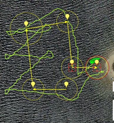
Coming home after an hour of autonomous sailing around the course.

A short mission, generally navigating a good track.


Note: This is part of the ongoing development of a low cost autonomous oceangoing sailing drones, utilising a self-trimming wingsail. This is the Voyager series of sailing drones.

Monday, 5 August 2019

Waterproofing a Standard Servo

Waterproofing a Standard Servo (well, splash proofing it at least)

The post describes a process I used to protect a standard servo against water.
The servo was a Hitec 919, but most servo use the same basic construction 
The main entry points for water below the mounting flange are protected by a spray coating.
The splined shaft is protected using grease on the inside of the casing and an O-Ring on the outside.

Details of the steps follow.

Step 1.
Partially disassemble the servo by removing the 4 screws from the bottom, and remove the top and bottom casings.


Step 2.
Slide out the Motor and PCB assembly.
Apply a Conformal Coating to the PCB to improve its resistance to water.
I didn't spay it directly, because I wanted to avoid any moving parts, but rather sprayed a few millilitres into a small container, and applied it to the PCB using a wooden ice cream stick.

Step 3.
Apply grease to the bearing area just below the splines.


Step 4.
Reassemble the servo.

Step 5.
Add an O-ring  (1mm by 4mm) to splines.

Step 6.
Use a file on the bottom of the servo arm splines, to increase the gap between the top of the servo housing and the servo arm.
The gap needs to be increased so there is enough room for the O-Ring when the Servo Arm is screwed down, without it being too tight ,and causing undue friction.


Step 7.
Apply a protective spray coating lower part of the servo below the mounting flange.
I used masking tape and Red Plasti Dip.

Unfortunately, I forgot to take a photo before installing the servo back into the Wingsail, and this photo is not good.


Monday, 29 July 2019

Magnetic Compass Errors Revisited - Wingsail Angle Sensor/Magnetic Disk

Magnetic Compass Errors Revisited - Wingsail Angle Sensor/Magnetic Disk

The Wingsail Angle Sensor incorporates a magnetic disk. Its located around 300mm from the Magnetic Compass. I thought this was a reasonable distance, but perhaps its interfering with compass.


Wingsail Angle Sensor Magnetic Disk

I set up a test to measure compass error versus wingsail angle and plotted the results.
They were bad.
The plotted results below, show that the wingsail angle is responsible for large errors of around 25 to 35 degrees  with a wingsail angle of 45 degrees.
Negative wingsail angle represents port tack.


The image below shows a successful completion of a course of waypoints, with a northerly wind
The reaching leg across the top of the course shows the vessel heading about 30 degrees to port of the desired course. It is pointing higher than necessary by about 30 degrees, due to compass error.

This is consistent with the measurements recorded in the graph above.
On the port tack the error is about +30 degrees.
Hence the vessel must reduce the heading angle by about 30 degrees to maintain the desired magnetic course.
Hence, in this case,  on the reaching leg, it is steering about 30 degrees to port.

Course Demonstrating Compass Error


Conclusions: 

It will be difficult to increase the separation between the magnetic compass and the magnetic disk on the wingsail on a vessel of this size (1.2m LOA).
It is likely that the wingsail magnetic disk is unnecessarily large and strong. So it will be necessary to test a smaller disk with a reduced number of magnets, to reduce the field strength, yet still maintain reliable operation of the wingsail angle sensor.


Note: This is part of the ongoing development of a low cost autonomous oceangoing sailing drones, utilising a self-trimming wingsail. This is the Voyager series of sailing drones.

Sunday, 28 July 2019

Waterproof Steering Coupling - Magnetic Coupling

Waterproof Steering Coupling - Magnetic Coupling

A magnetic coupling is used to transmit the Steering Servo movement out of the water tight compartment to the rudder pushrod.

This has been successful.
In the correct configuration, all six magnet pairs are engaged.
It can suffer the problem that the outside disk can be forced to detent in the wrong place, one sector in either direction.
In this position, two magnet pairs are attracting and four are repelling. 
It is a semi-stable state, but it can easily be pushed back to the corrected alignment.

The pattern of magnetic orientation has an effect on behaviour, and more study is required to determine the best arrangement and quantity of the magnets.
Perhaps less magnet pairs are better, because the angle to next detent point would be greater with a reduced number of magnets.
This would need to be balanced against the reduced magnetic coupling with the reduced number of a magnets.


Lower Magnetic Coupling Disk fitted to the Rudder Servo


Complete Magnetic Coupling Assembly


Thursday, 25 July 2019

Wingsail Angle Sensor

Wingsail Angle Sensor 

The vessel does not have any explicit wind sensors for measuring wind speed or wind direction.
All sailing navigation decisions rely on knowing the angle of the self-trimming wingsail against the hull.
The wingsail angle is measured using the MPU9250 IMU as a magnetic sensor, and magnetic disk attached to the wingsail.
The MPU9250 may be an overkill for a magnetic sensor, however they do have benefits:
  • I2C bus, so it easily interfaces to the Arduino microprocessor.
  • Sensitive as a magnetic sensor, allowing good separation distance to the magnetic disk
  • The MPU9250 was difficult to use as an actual magnetic compass because it was difficult calibrate and use. They are easy to use as a magnetic angle sensor however. They are not expensive and I have a few to spare.

Wingsail Angle Sensor with Wingsail Magnetic Disk

 The housing for the Wingsail angle sensor is a 3D printed shape that is integrated with the Mast Tube deck plate. 
Magnetic Sensor Housing fixed in place. 
The magnetic disk is attached to the wingsail, so that the magnetic field created by the disk rotates with the sail The disk consists of a 3D printed holder for an array of about 60 cylindrical magnets 2mm diameter, 10mm long. Its obviously important that all of the magnets have the same orientation.

3D model of the Wingsail Magnetic Disk 

Future design changes:
  •  Integrate the Magnetic Disk more tightly with the Wingsail, possibly by incorporating it with the bottom foil section.
  • Add a duplicate MPU9250 Wingsail angle sensor for redundancy. 

Note: This is part of the ongoing development of a low cost autonomous oceangoing sailing drones, utilising a self-trimming wingsail. This is the Voyager series of sailing drones.

Thursday, 18 July 2019

Compass Heading Error Correction using GPS

Compass Heading Error Correction using GPS

(or GPS/Magnetic Compass Fusion)


Magnetic compass calibration is constant problem, but if we assume the GPS Course of Ground (COG) represents the actual heading of the vessel, then we can establish a difference between the two sensors, and apply a correction to the compass.
Of course, we can only assume the GPS COG is correct if we assume there is no movement of the water. That is, no tidal flow or currents.

The GPS COG is only valid when the GPS is moving. The COG provided by a stationary GPS device tends to point in all directions is has little meaning.
Hence, the COG can only be used to establish a Compass heading error if the GPS Speed of the Ground (SOG) is above a reasonable level.

The procedure below is currently in use, and forms Compass error value based on the GPS COG, when the SOG is greater than 0.2 m/s.
The resulting error is passed through a low pass filter to dampen its movement and then applied to the measured Compass Heading.


void NavigationUpdate_FastData(void)
{
 // Calculate True Heading From Magnetic Heading.
 // This is expected to be called from a fast loop .
 // about 50ms
 // V1.0 31/10/2016 John Semmens
 // V1.1 6/4/2019 added CompassOffsetAngle for handling mounting orientation
 // V1.2 11/7/2019 added Heading Error calculation and correction.


NavData.HDG_Mag = int(wrap_360(myIMU.heading + Configuration.MagnetVariation + Configuration.CompassOffsetAngle));

 // calculate and error value from the GPS and dampen it using low pass filter
 int RawHeadingError;
 if (NavData.SOG_mps > 0.2) // if the SOG is reasonable then assume the
 {
  RawHeadingError = wrap_180(NavData.HDG_Mag - NavData.COG);
 }
 else
 {
  RawHeadingError = 0;
 }

 // apply a low pass filter
 NavData.HDG_Err = HeadingErrorFilter.Filter(RawHeadingError);


 NavData.HDG = int(wrap_360(NavData.HDG_Mag - NavData.HDG_Err));

}


The GPS based compass correction has made a noticeable difference on the water.
The image below depicts the longest mission to date for the vessel. The wind is from the NNW.
The image clearly shows that the vessel has steered accurately to the waypoints on the downwind legs.
The longest course so far, incorporating GPS Based Compass Correction

The image below shows a similar, but shorter course, that was completed prior to the GPS based compass compensation.
The image shows that the vessel is steering significantly to the left as it approaches each waypoint that it can sail to without tacking.
A previous course successfully completed, without GPS compensation for the Compass 


And of course a photo from today's sailing...

Note: This is part of the ongoing development of a low cost autonomous oceangoing sailing drones, utilising a self-trimming wingsail. This is the Voyager series of sailing drones.

Sunday, 14 July 2019

Wingsail in Strong Winds - Photos

Strong Wind, Flat Water Sailing - Photos 

These are just some photos from testing today in gusty winds up to about 20 knots.

Consideration will be given to using an average roll angle (heel angle) as a control over the Wingsail Trim Tab angle as a means to de-power the sail in strong winds, in future updates.

Beating off a lee shore


Laid flat by a bullet


Well behaved while beating with a constant wind direction

This sailing trial included the new Wingsail Bluetooth controller built using the dedicated PCB. The new Bluetooth controller behaved well.


This is part of the ongoing development of a low cost autonomous oceangoing sailing drones, utilising a self-trimming wingsail. This is the Voyager series of sailing drones.

New PCB for Bluetooth Sail Controller

New PCB for Bluetooth Sail Controller


The sailing trials continue in fresh water, but the aim is to put to sea.
The electronic systems need a lot of hardening to survive a saltwater environment.

One step in the process is the development of a dedicated PCB for the Wingsail controller.
The new PCB incorporates:
  •  On-board ATMega328p with the Arduino Pro Mini bootloader, rather than a separate Arduino module.
  •  Support for a Dual Servo Outputs, although only one is populated.
  • Support for switching an auxiliary 5Vdc load. I'm thinking of an LED Strobe or lights to aid night time operations.
  • Solar Charging circuitry using the LTC3105, also currently not populated.
The justification for adding solar charging to the Wingsail Controller is not great.
Testing suggests that the Wingsail Controller cells can operate for about 8 days on a single charge. The current Voyager Controller for can only operate for a couple of days in the current configuration. There will be more discussion on that in future posts as efforts are made to improve battery life, prior to engaging solar charging for the vessel.

The competed PCB operated faultlessly There were no errors in the PCB design, which is what is was worried about of course. For some reason, the Arduino takes an extra second or two to boot up when compared the prototype design using the Arduino Pro Mini module. It doesn't really matter, but I'd like to understand the reason, when I have time to investigate.

The competed PCB was sprayed with about a dozen coats of Conformal Coating to provide some protection from the environment.


 The new production Bluetooth Sail Controller PCB with conformal coating and mounted ready for installation in the wingsail.


Note: This is part of the ongoing development of a low cost autonomous oceangoing sailing drones, utilising a self-trimming wingsail. This is the Voyager series of sailing drones.

Sunday, 30 June 2019

Sailing the Course with a Calibrated Compass

Sailing the Course with a Calibrated Compass

48 hours after the successful first completion of the sailing course, we're back to repeat the course; but this time, with the compass calibrated (better than it was previously, anyway).
The sailing performance was much better.
The wind was about 10-12 knots from the NNW.

Sailing the course much more efficiently this time.


The current settings for minimum Apparent Wind Angle (AWA) while beating to windward is 45 degrees. The log results show that this resulted in tacking angles of 105 degrees.


Sailing the last leg in about 10 knots of wind.

The next steps in development should include preparing a polar diagram of performance of the vessel.

Saturday, 29 June 2019

First Completion of a Sailing Course - No Hands!

First Completion of a Sailing Course - No Hands!

After recent revisions of the onboard software I was able to run another test after work and this time successfully completed a sailing course with no manually intervention.

At any time, while in range, I can switch on an RC Transmitter and take over manual control of the boat, and then revert back to following the mission or several other options. I've often needed to do this previously to recover the boat from situations caused by errors in my software.
This was the first time that the boat has completed a course while sailing, with no manual intervention.

The course involved 6 waypoints with running, reaching and beating, with a light wind from the NNE.
The Short Sailing Course just completed. 


I'll need to study the logs very carefully, but the initial impression is that the software behaved ok, but compass calibration is a big problem, with errors of up to 40 degrees.
The large compass error meant that the course sailed was not very good. The marks were overlaid and underlaid, causing excessive tacking. But at least the software was resilient enough to get it around the course.


Nearing the Last Waypoints after Sunset


Monitoring Progress in Real-Time through the Telemetry


Note: This is part of the ongoing development of a low cost autonomous oceangoing sailing drones, utilising a self-trimming wingsail. This is the Voyager series of sailing drones.

Sunday, 23 June 2019

Electronic Compasses for Voyager

Electronic Compasses for Voyager

I'm losing count, but I think its about 5 different compass devices I've trialled during the development of the Voyager Controller - so far.

The image below shows a mild case of the problem of compass accuracy.
The leg with a bearing of about 350 degrees from first to second waypoints shows the boat heading off on a bearing of about 330 degrees with about 20 degrees error.
It still gets there, but its not good.

A successful voyage under motor, but poor compass accuracy

Measuring the boat's heading accurately has been quite difficult.
Overall, I suspect it all comes down to calibration, and the built-in mechanisms to manage calibration in a way that actually works in the environment in which it will be used.
The following is a list of the different compass devices that made it into the Voyager Controller and my thoughts about them.
These notes represent my understanding of what's going on. If I can be corrected, then good.

MPU-9250 - August 2016

This is quite a good low-cost IMU device for measuring 9 degrees of freedom including 3-axis magnetic sensing. It requires all sensor fusion and calibration management to be handled by the host processor.
The problem I had was that I could not get any sensor fusion and calibration software sample that I could find to work satisfactorily. (This may be attributed to my impatience or incompetence).
I'm sure it may be possible, but there are more complete (and expensive) devices available which perform the sensor fusion and calibration maintenance on board.

Note: I now use the MPU-9250 device as magnetic rotation angle sensors. This is where a rotating device (like the Wingsail) has a magnet held near the MPU-9250, and its angle is measured. The magnet can easily swamp the effect of the earth's magnetic field and the resulting accuracy of the rotational measurement seems to be within 1 or 2 degrees.

BNO 055 - October 2017

This was the first IMU I tried with built-in sensor fusion.
The sensor fusion worked quite well, but magnetic calibration was not being maintained and it kept drifting off.

BNO 080 - October 2018

This seems to have improved accuracy over the BNO 055. Its built-in calibration processes continuously seem to perform calibration of the compass as it moves.
The problem that I could not solve, was that it continues to perform those calibrations when its not moving then starts drifting off for no apparent reason.
The end result seems to be that with the boat sitting stationary on ground, and after preforming some calibration motions to achieve a high-level of calibration, it simply starts to drift off by 20 or 30 degrees.
My understanding is that this behaviour can't be controlled.

Ultimate Sensor Fusion Solution - LSM6DSM + LIS2MD - April 2019


This device has been the most successful yet.
It incorporates onboard sensor fusion processing and calibration management.
One key point is that the calibration is well controlled, and seems to be better behaved.
Small movements of the boat seem to be enough to maintain the compass calibration.
It is also possible to save a calibration state, and reload it for a warm start.
I found the documentation and sample code to operate this device couldn't be directly used in my environment without the need to gain a better understanding of the operation of the device. Once I had gained enough understanding of the device, I was able to alter the sample drivers software to suit my requirment. This wasn't really necessary with most of the other devices I've used.

Lots of Sailing Trials

Lots of Sailing Trials - February to June 2019

The sailing hardware and electronic hardware has been quite stable for several months while I work on refining the sailing algorithms. The nearby lake has a good fetch from the North West, and so NW winds are the best for sailing trials. Each week I make changes to the sailing software, and perform trials, trying improve the sailing and tacking decisions as the boat moves through its waypoints.


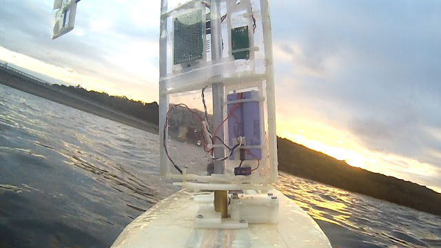
On-board camera showing the back of the Wingsail Electronics


Sunset Trials after work

Programming a mission before commencing a run


10-15 knot breeze 

Many of the parameters from the onboard controller are transmitted in real-time back to the base station for visualisation. More parameters are recorded on an SD Card that can be reviewed in greater detail back at home.  I found it quite difficult to analyse the masses of data I was collecting by simply studying the raw log files, and so an additional Log Analyser was developed where the log files could be visualised and played back (both backwards and forwards) to study the details of the sailing decisions that were being made.
I found this vital to moving forward and resolve some the bugs in the sailing algorithms.

Log Analyser for replaying details


Note: This is part of the ongoing development of a low cost autonomous oceangoing sailing drones, utilising a self-trimming wingsail. This is the Voyager series of sailing drones.