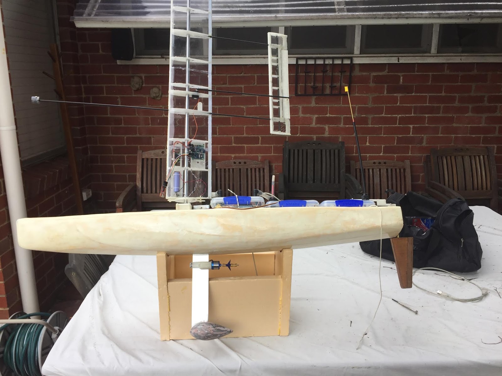
Voyager 2.0 Wingsail with Bluetooth Controller
Monday, 1 October 2018
Sunday, 8 July 2018
Voyager 1.5 - Build, Launch and Voyage
Voyager 1.5 - Build, Launch, Voyage and Loss.
Following the voyage of Voyager 1 out near Lord Howe Island, I was provided with another unwanted model yacht hull, that I could send offshore.
This time I could employ some the lessons learned from Voyager 1 in the preparation of Voyager 1.5.
The main change was the use of closed cell construction foam to pack the hull and ensure that it is intrinsically buoyant. I want to ensure it doesn't sink.


Another change was the use of larger batteries for the Satellite Transmitter, changing from AA Cells to C Cells. This should yield an estimated 6 months of operating time.
Voyager 1.5 was launched from Woodside Beach in Gippsland Victoria, as per Voyager 1.
Once a suitable weather window arrived, it was launched on 13/6/2018.

Another change was the use of larger batteries for the Satellite Transmitter, changing from AA Cells to C Cells. This should yield an estimated 6 months of operating time.
Voyager 1.5 was launched from Woodside Beach in Gippsland Victoria, as per Voyager 1.
Once a suitable weather window arrived, it was launched on 13/6/2018.
The position reports were logged on this page http://ww2.acaciacs.com.au/voyager1.5/.
Progress was slow and after about 2 weeks, Voyager 1.5 hadn't entered the Tasman Sea.
Finally, a big Westerly gale arrived on July 7. This started to push Voyager 1.5 out into the Tasman Sea.
However, at 4am the next morning. the last satellite transmission was received.
What had happened ?
The signal was lost during a gale with winds approaching 50 knots from the West.
That implies that the signal lost due to some sort of breakage.
Possible reasons why it is no longer transmitting:
- There has been electrical failure
- The has been a breach of the water tight container holding the SPOT GPS, and it has been damaged by the salt water.
- The Hull has broken up or been damaged in the gale, and the SPOT GPS does not have a clear view of the sky
We may never know....
Friday, 23 February 2018
Voyager 2.0 Controller Evolution
This series of photo illustrates the evolution of the Voyager Controller design so far.![]() |
| November 2016 - They're not called "Breadboards" for nothing |
![]() |
| October 2018 - Veroboard Design |
![]() |
| January 2019 - More compact and robust 3D Printed Chassis |
![]() |
| January 2019 |
| March 2019 - New PCBs !! |
![]() |
| April 2019 - The first dedicated PCB Design |
Thursday, 23 February 2017
Voyager 2.0 Hull
Voyager 2.0 Hull
The hull was design using Freeship.
This is very powerful free hull design software.
The hull design was not intended to be sophisticated, just a simple balanced hull providing good buoyancy fore and aft.
Once the design was settled, lines were exported and transcribed on the 3mm marine ply to be used as stringers, glued between the closed cell construction foam.
The foam board used was available in 50mm sheets, 1200mm long. This was the main parameter for determining the hull dimensions for Voyager 2.0.
Six pieces of foam were cut to shape to follow the lines from hull design.
They were all to be glued together with the plywood stringers in between using one part polyurethane glue.
It was found that the stringers were not needed, except for the central one incorporating the mast bearing tube and centreboard casing. The use of plywood stingers between the foam board would have made the hull far heavy than desired, and unnecessarily solid.
![]() |
| Screen shot of the hull lines in the Freeship program. |
![]() |
| Central Plywood stringer part way through construction. It will incorporate the Centreboard Casing and Mast Bearing Tube |
![]() |
| Closed Cell Foam Construction Board 1200mm long by 50mm thick |
![]() |
Shaped Hull being weighed, prior to Fibreglassing
|
The fibreglass cloth used was rated at 2 ounces.
Epoxy resin was used. (Polyester dissolves the foam. A lesson I stupidly learnt the hard way!)
![]() |
| Preparing to Layup the Fibreglass |
| First float test |
Note: This is part of the ongoing development of a low cost autonomous oceangoing sailing drones, utilising a self-trimming wingsail. This is the Voyager series of sailing drones.
Tuesday, 31 May 2016
Voyager 2.0 - Design Principals and Construction Methods
Design and Construction Principals to be applied to Voyager 2
Hull Construction
The vessel should be intrinsically buoyant and unsinkable.It was decided to build the hull using surfboard construction methods of glass fibre coth with epoxy resin over a closed cell foam.
The hull will be built using sheets of construction foam sandwich glued with plywood stringers. The stringers would be cut to match the appropriate offset lines from the hull design drawings. Then the foam could be carved down to match plywood stringers and sanded and then glassed.
Hull Design
The hull would designed using Freeship. This is powerful, free, hull design software. It has reasonable export capabilities extracting lines and offset information.
Rudders
Standard RC Servos will be used for the rudder (or rudders). These have a limited life, mostly constrained by the wear of the feedback potentiometer. It seems that low cost servos have a single wiper within the potentiometer whereas longer life servos use potentiometers with multiple wipers (typically 3).
One way of doubling the life of a servo is to use it half the time.
Voyager 2 will only have a single rudder, but a later version of voyager will use two rudders, operated by two servos. The steering will be performed by the leeward rudder, while the windward rudder will remain centred.
Sail
The sail will be self trimming wing sail.
This type of sail is particularly good for low powered autonomous vessels, because it takes very little power to operate the trim tab to set the sail.
Traditional soft sails or a traditional solid sail typically require a fairly powerful winch or machinery to control.
Keel
One of the hazards to vessels is floating weed.
It is critical that the design of the keel and rudder will shed weed, rather than catch it.
This generally involves using profile with a gentle rake on the leading edge of the keel and rudder skeg to allow the weed slide off.
This also tends to lead to a the use of a unbalanced rudder attached to the sloping rudder skeg.
Equipment Housing and Equipment Bay
The Sistema plastic containers are reasonable for use as equipment housings.
They are reasonably waterproof for short term usage, but can be sealed using a non-corrosive silicone sealer if a completely water tight compartment is required.
It was decided that Voyager 2 would have an equipment bay located aft of the keel assembly, all the way to the back of the vessel with an open transomn.
Sunday, 29 May 2016
Servo Endurance - Test Results
Hextronik HXT900
Two model HXT900 servos were tested. Both failed at approximately 40,000 cycles.
The component that failed was the potentiometer, which developed dead spots.
The Servo could continue to be used if the operating region was changed to a different position on the potentiometer.
The image below shows the potentiometer removed from one of the failed servos, showing the worn area. This potentiometer has two wipers.
Two model HXT900 servos were tested. Both failed at approximately 40,000 cycles.
The component that failed was the potentiometer, which developed dead spots.
The Servo could continue to be used if the operating region was changed to a different position on the potentiometer.
The image below shows the potentiometer removed from one of the failed servos, showing the worn area. This potentiometer has two wipers.
![]() |
| HXT900 Potentiometer showing Wear |
Arduino Servo Endurance Tester
How long do RC servos last ?
The RC servo manufacturers don't seem to publish any information about the operational life span of their servos. The life span of a servo will be influenced by the amount of loading, both static and dynamic. But there'is a fundamental limit which is the number of cycles with no load.
It seems that the quality of feedback potentiometer, rather than the drive train or motor is the limiting factor for the maximum number of cycles an RC servo can perform.
This is a design for a very simple RC Servo exerciser to cycle a servo 20 degrees either side of neutral about once per second. It includes an I2C LCD 2 line by 16 character display to display a count of cycles.
The code for the Arduino is provided below:
#include "LiquidCrystal_I2C.h"
#include <Wire.h>
#include <Servo.h>
Servo myservo; // create servo object to control a servo
int pos = 0; // variable to store the servo position
// Set the LCD address to 0x27 for a 16 chars and 2 line display
LiquidCrystal_I2C lcd(0x27, 16, 2);
long CycleCounter = 0;
int BasePosition = 90;
void setup()
{
// attach the servo on pin 9 to the servo object
myservo.attach(9);
// initialize the LCD
lcd.begin();
// Turn on the blacklight
lcd.backlight();
lcd.clear();
}
void loop()
{
myservo.write(BasePosition); // tell servo to go to Base Position
delay(400);
myservo.write(BasePosition+20); // move + 20 degrees
delay(300);
myservo.write(BasePosition-20); // move - 20 degrees
delay(300);
CycleCounter++;
lcd.setCursor(0, 0);
lcd.print(CycleCounter);
}
The YouTube clip below shows the test rig in operation with an initial test using a low cost servo. It lasted for about 40,000 cycles before failure. I'll discuss the results of servo tests in another post.
The RC servo manufacturers don't seem to publish any information about the operational life span of their servos. The life span of a servo will be influenced by the amount of loading, both static and dynamic. But there'is a fundamental limit which is the number of cycles with no load.
It seems that the quality of feedback potentiometer, rather than the drive train or motor is the limiting factor for the maximum number of cycles an RC servo can perform.
This is a design for a very simple RC Servo exerciser to cycle a servo 20 degrees either side of neutral about once per second. It includes an I2C LCD 2 line by 16 character display to display a count of cycles.
![]() |
| Servo Test Rig showing Arduino Nano, I2C LCD and Test Servo |
The code for the Arduino is provided below:
#include "LiquidCrystal_I2C.h"
#include <Wire.h>
#include <Servo.h>
Servo myservo; // create servo object to control a servo
int pos = 0; // variable to store the servo position
// Set the LCD address to 0x27 for a 16 chars and 2 line display
LiquidCrystal_I2C lcd(0x27, 16, 2);
long CycleCounter = 0;
int BasePosition = 90;
void setup()
{
// attach the servo on pin 9 to the servo object
myservo.attach(9);
// initialize the LCD
lcd.begin();
// Turn on the blacklight
lcd.backlight();
lcd.clear();
}
void loop()
{
myservo.write(BasePosition); // tell servo to go to Base Position
delay(400);
myservo.write(BasePosition+20); // move + 20 degrees
delay(300);
myservo.write(BasePosition-20); // move - 20 degrees
delay(300);
CycleCounter++;
lcd.setCursor(0, 0);
lcd.print(CycleCounter);
}
The YouTube clip below shows the test rig in operation with an initial test using a low cost servo. It lasted for about 40,000 cycles before failure. I'll discuss the results of servo tests in another post.
Voyager 1 - Why did it disappear ? Conclusions. or A Study of the Water Take-up Rates with Different Foam Types.
Voyager 1 - Why did it disappear ? Conclusions.
A Study of the Water Take-up Rates with Different Foam Types.
I suspect Voyager 1 sank off Lord Howe Island due to the take-up of water into the spray foam, which was used as primary buoyancy.
The test this hypothesis, I set up a test using samples of foam with a standardised size of 10cm x 10 cm x 10cm (1litre). These were held in water for several weeks. The foam samples were weighed daily and the results were plotted.
The Construction Foam (closed cell) gained a couple of grams of water in the first day or two, and then its weight did not noticeably change for the next 40 days.
The Spray Foam (open cell) gained weight through out the 40 day test. The samples of Spray Foam gained between 150g and 190g of water during the test. This represents 15% to 19% by volume of the foam.
I suspect that this take-up of water into the spray foam buoyancy caused the vessel to sink; and this was the most likely reason for the loss of signal.
A Study of the Water Take-up Rates with Different Foam Types.
I suspect Voyager 1 sank off Lord Howe Island due to the take-up of water into the spray foam, which was used as primary buoyancy.
The test this hypothesis, I set up a test using samples of foam with a standardised size of 10cm x 10 cm x 10cm (1litre). These were held in water for several weeks. The foam samples were weighed daily and the results were plotted.
![]() |
| Two Foam Samples created from Spray Foam (Open Cell). |
![]() |
| Sample of Construction Foam (Closed Cell). |
![]() |
| Test Rig - Two Buckets of Water and Bricks. |
![]() |
Weight Gain of the Foam while held in water over 42 days.
|
The Spray Foam (open cell) gained weight through out the 40 day test. The samples of Spray Foam gained between 150g and 190g of water during the test. This represents 15% to 19% by volume of the foam.
I suspect that this take-up of water into the spray foam buoyancy caused the vessel to sink; and this was the most likely reason for the loss of signal.
Saturday, 28 May 2016
Voyager 1 - The Last Signal
The Last Signal was received on May 28, 2016 at 1:38am.
http://ww2.acaciacs.com.au/voyager1
The boat was approaching Lord Howe Island at approximately 2 knots at a distance of 110km, when it sent its last transmission.
It had travelled about 1200km from the launch point in Gippsland, Victoria, over 28 days.
What happened ?
We will probably never know what happened to the boat, because we will probably never see it again.
Possible reasons why it is no longer transmitting:
The Last Signal was received on May 28, 2016 at 1:38am.
http://ww2.acaciacs.com.au/voyager1
The boat was approaching Lord Howe Island at approximately 2 knots at a distance of 110km, when it sent its last transmission.
It had travelled about 1200km from the launch point in Gippsland, Victoria, over 28 days.
| Approaching Lord Howe Island when the last signal was received. |
What happened ?
We will probably never know what happened to the boat, because we will probably never see it again.
Possible reasons why it is no longer transmitting:
- It has sunk
- The batteries are flat
- There has been electrical failure
- The has been a breach of the water tight container holding the SPOT GPS, and it has been damaged by the salt water.
- The SPOT GPS does not have a clear view of the sky.
Wednesday, 25 May 2016
Voyager 1 - The Voyage
Launch May 1st 2016 - Woodside Beach, Victoria
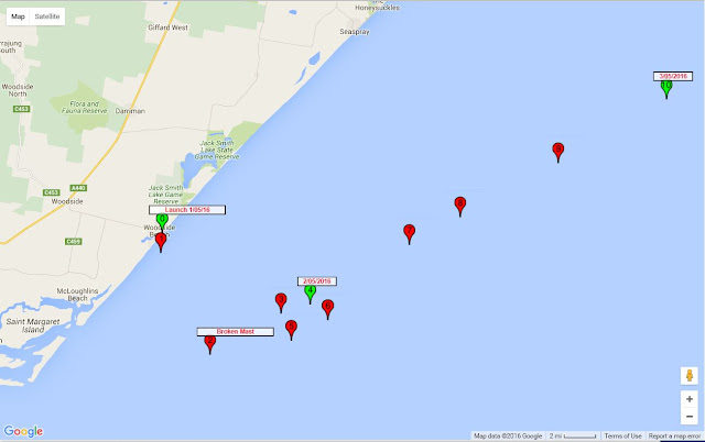
This launch of Voyager 1 was successful. Follow its path here. The prevailing weather conditions were good for taking the boat well offshore. The offshore winds were due to continue for at least a week, with a series of westerly fronts coming through Bass Strait. This should have been good for fulfilling the plan of getting boat well offshore and down into the southern Tasman Sea.| Setting up on the Beach |
![]() |
| Final Preparations |
![]() |
| The Launch |
The boat sailed well for the first 8 hours in a SSW direction.
This was ahead of the first of a series of westerly fronts coming in the next week.
The impending westerly wind should have caused the boat to change course from SSW to about WSW.
But it appears to have headed NW instead; and it appeared to travelling upwind at times.
| The First Two Days |
This pattern of movement implies that the boat stopped moving with relation to the wind, and instead started moving with the currents instead.
This implies that the mast was broken and the sail is in the water helping to act as a sea anchor, causing the boat to move with the current, and not be influenced by the wind.It appears that mast was broken when the first front came through on the evening of May 1st 2016.
The weather fronts caused significant damage to properties around Melbourne on the evening of the Launch. News reports of the weather can be seen on The ABC and in The Age.
What was learnt ?
It is an assumption, that the mast is broken, but its hard to imagine another explanation.
The mast was mostly un-stayed, 1m long, 12mm aluminium tubing, with a wall thickness of about 1mm. If it broke, then it was clearly not strong enough for the boat in the conditions experienced.
It will be necessary to consider ways of mitigating this problem in future offshore model boats.
The Flinders Current
The boat is no longer a sailing vessel headed into the southern Tasman Sea as planned. Instead, it is now a drifting buoy, with a Satellite tracking facility.
For the first few days, it travelled fairly distinctly up the Gippsland Coast in a NW direction.
This corresponds to part of the current known as the Flinders Current.
The Flinders Current flows in easterly direction across the south of Australia. It partly flows through Bass Strait, and partly flows up the Gippsland Coast.
This what is moving the boat for the first week.
End of Week 2: May 15, 2016
After 2 weeks at sea, the boat has continued to travel in NW direction up the east Australian coast. At this time it was located over 350km offshore, just south of Sydney.
It movement is under the influence of East Australian Current (EAC). The EAC flows south down the east coast of Australia, close to the mainland down to about the latitude of Sydney. It predominantly flows offshore to the east, at about that point, heading into the Pacific. The edges of the EAC are dominated by eddies that cause significant wandering and circling of the current flow.
May 25 - 25 Days at Sea
After 25 days, the boat is about 1000km from the launch point and about 400km offshore, east of Newcastle. It appears to be on course to drift passed Lord Howe Island and continue into the Pacific. We'll see.
The SPOT GPS Satellite tracking facility is still going well. Without it, We'd have nothing.
Voyager 1 - The Launch Attempts - Learn Something New Every Time
First Launch Attempt 14 January 2016 - Near Pambula, NSW
This launch failed.
Primarily because, the weather conditions did not provide enough of an off-shore breeze for the boat sail away from shore.
The boat was damaged by breaking waves.
This provided guidance on changes in the design and construction of the boat.
The damage incurred was that the Aluminium Fin bent 90 degrees when the boat was caught in a breaking wave.
What was Learnt ?
The Fin bent so easily, that is fortunate that the launch failed. If the boat had successfully sailed offshore, the fin would have bent in the first storm, leaving the boat lying on its side in the water. In this condition, the SOPT GPS satellite tracking facility would not have worked very well, the boat would have been effectively lost.
The Wind Vane rotated on the shaft when the boat was engulfed by the breaking wave. This is equivalent to changing the course setting of the Vane Steering gear. Hence if a reliable sailing course is to be maintained, steps must be taken to prevent the Wind Vane from rotating on the shaft.
What changes were made ?
The fin was strong enough to support a static load, but bent easily under the dynamic load of a breaking wave.
The fin was reduced in length to about half the original length.
The Wind Vane mounting arrangements were initially fabricated in 3D printed ABS plastic.
The 3D printed plastic bosses had threads cut for the 5/32" set screws that were intended to lock the bosses on to the brass shaft.
These worked ok, and could resist quite high static torque loads, but in the conditions experienced with a breaking wave, they easily slipped from the set position.
The second version, included threaded metal components. This allowed much torques to be applied to the set screws to resist slipping.
Second Launch Attempt February 15 2016 - Woodside Beach, VIC
This launch was partly successful.
The boat sailed well in a light offshore breeze, and launch appeared successful.
The boat was retrieved for reworking in preparation for the next attempt.
What Went Wrong ?
My assessment of the weather was wrong. I had assumed the offshore breeze would continue for a much longer period and get the boat further offshore into the prevailing breeze.
But instead, it end up back on the beach.
What was Learnt ?
The weather predictions must not be marginal in any way. If there is any uncertainty, then its best not to launch.
There was some damage when boat came ashore. The polycarbonate Wind Vane was broken, the brass Wind Vane shaft was slightly bent, and the Wind Vane bronze bearing was dislodged from its housing.
What changes were made ?
The vertical shaft for Vane was changed from brass to stainless steel. This was done because of concerns about the brass shaft bending. Stainless steel is almost double the hardness of brass. Hence the replacement stainless steel shaft is much more resistant to bending.
The Wind Vane was made using 2mm polycarbonate sheet. This was broken during the beaching. It was replaced with 1mm carbon fibre sheet. This is considerably stronger and also about 60% of the mass of the polycarbonate sheet.
The weight reduction of the Wind Vane required a rebalancing of the vane assembly, and hence their was a corresponding reduction in the lead counterweight.
This launch failed.
Primarily because, the weather conditions did not provide enough of an off-shore breeze for the boat sail away from shore.
The boat was damaged by breaking waves.
This provided guidance on changes in the design and construction of the boat.
The damage incurred was that the Aluminium Fin bent 90 degrees when the boat was caught in a breaking wave.
What was Learnt ?
The Fin bent so easily, that is fortunate that the launch failed. If the boat had successfully sailed offshore, the fin would have bent in the first storm, leaving the boat lying on its side in the water. In this condition, the SOPT GPS satellite tracking facility would not have worked very well, the boat would have been effectively lost.
The Wind Vane rotated on the shaft when the boat was engulfed by the breaking wave. This is equivalent to changing the course setting of the Vane Steering gear. Hence if a reliable sailing course is to be maintained, steps must be taken to prevent the Wind Vane from rotating on the shaft.
What changes were made ?
The fin was strong enough to support a static load, but bent easily under the dynamic load of a breaking wave.
The fin was reduced in length to about half the original length.
The Wind Vane mounting arrangements were initially fabricated in 3D printed ABS plastic.
![]() |
| Version 1 - Almost Fully 3D Printed Vane Steering Gear |
The 3D printed plastic bosses had threads cut for the 5/32" set screws that were intended to lock the bosses on to the brass shaft.
These worked ok, and could resist quite high static torque loads, but in the conditions experienced with a breaking wave, they easily slipped from the set position.
![]() |
| Version 2 - More Metal Components added |
The second version, included threaded metal components. This allowed much torques to be applied to the set screws to resist slipping.
Second Launch Attempt February 15 2016 - Woodside Beach, VIC
This launch was partly successful.
The boat sailed well in a light offshore breeze, and launch appeared successful.
![]() |
| An Apparently Successful Launch at Woodside Beach |
The first satellite signal was received after about 20 minutes when the boat was about 1 kilometre offshore. But 4 hours later the next signal showed the boat was on the beach several miles up the coast.
![]() |
| Satellite Position Signals showing the Launch from Woodside Beach and then running ashore several miles up the Beach. |
![]() |
| Washed up on the Beach like a dead Sea Gull |
The boat was retrieved for reworking in preparation for the next attempt.
What Went Wrong ?
My assessment of the weather was wrong. I had assumed the offshore breeze would continue for a much longer period and get the boat further offshore into the prevailing breeze.
But instead, it end up back on the beach.
What was Learnt ?
The weather predictions must not be marginal in any way. If there is any uncertainty, then its best not to launch.
There was some damage when boat came ashore. The polycarbonate Wind Vane was broken, the brass Wind Vane shaft was slightly bent, and the Wind Vane bronze bearing was dislodged from its housing.
What changes were made ?
The vertical shaft for Vane was changed from brass to stainless steel. This was done because of concerns about the brass shaft bending. Stainless steel is almost double the hardness of brass. Hence the replacement stainless steel shaft is much more resistant to bending.
The Wind Vane was made using 2mm polycarbonate sheet. This was broken during the beaching. It was replaced with 1mm carbon fibre sheet. This is considerably stronger and also about 60% of the mass of the polycarbonate sheet.
The weight reduction of the Wind Vane required a rebalancing of the vane assembly, and hence their was a corresponding reduction in the lead counterweight.
Saturday, 21 May 2016
Voyager 1 - First Sea Trial on Port Philip
The first sea trial of Voyager 1 was performed on Port Philip.
The winds were light and sea was calm, which does not represent typical ocean conditions.
It sailed well and the Vane Steering performed well in the light conditions.
The winds were light and sea was calm, which does not represent typical ocean conditions.
It sailed well and the Vane Steering performed well in the light conditions.
![]() |
| Voyager 1 on Port Philip in light winds |
| Voyager 1 with Go Pro style Camera on board |
Subscribe to:
Posts (Atom)