Saturday, 25 May 2019

Minimal ATMega328P - common error

Minimal ATMega328P - common error  - won't run at 3V3.

I've started using ATMega328P as a minimal version  of the Arduino Pro Mini operating a 3Vdc.
I have been breadboarding circuits using the various articles published on the Internet as a guide for the minimal wiring required for running an ATMega328P as an Arduino.

The problem I suffered was that the circuits would happily run at 5Vdc, but stop running as the voltage was reduced to 3.3Vdc.

There seems to be a lot of discussion about the problem on forums; with almost none of it relevant to me.

Eventually I realised the silly mistake that I was making, by taking minimal circuits from Internet without checking the details for myself.

Many articles for minimal ATMega circuits leave AVCC open, rather than tying it to VCC.
If AVCC is left open, the ATMega will work at 5Vdc but will stop working at around 3.5Vdc.
Once connected to VCC, the ATMega will work below 3Vdc.

In my case, it worked down to about 2.7Vdc, which is one of the settings for the Brown Out Detector, so I suspect, that is what has come into play.


Friday, 24 May 2019

Slave I2C Interface for Serial GPS using Arduino Pro Mini 328P

Slave I2C Interface for Serial GPS using Arduino Pro Mini 328P


This post contains the code for creating a slave I2C device using an Arduino for a GPS receiver.
Hardware serial ports are precious on ATMega devices and I don't have enough available in my project to use on a GPS receiver, despite using an ATMega2560.
Software serial ports are often ok, but can suffer compatibility issues with other libraries in larger projects, and this has been prohibitive for me.
You can buy I2C GPS devices, and I do prefer to use them, but the one I was using failed, and I needed a quick solution to get my project back on the water without having to wait the 2 or 3 weeks for a replacement I2C GPS to arrive.
So, after an evening's research I was able to create a working I2C slave device using an Arduino Pro Mini 328P and integrate it with a regular serial GPS receiver.

The Arduino Pro Mini 328P running is at 16MHz and 3V3. Yes, I know its outside of specification with that combination of voltage and clock speed.

Overview

This simple sketch uses the very excellent TinyGPS++ to parse the GPS serial data and load the GPS object. Then we copy individual field values into our GPS structure which is mapped to linear Data buffer using UNION statement.
The Data buffer is then written out to the I2C interface in response to an I2C request.

Wiring

The Tx Pin from the GPS is connected to the RX pin of the Arduino Pro Mini 328P using a 1k resistor. This provides isolation to allow the Arduino to be programmed over the serial interface while the GPS is connected. If this were a direct connection, serial programming of the Arduino would not be possible without disconnecting the GPS.

Slave I2C GPS sketch


/*
    Name:       I2C_GPS.ino
    Created: 2 May 2019
    Author:     John Semmens
 Slave I2C Interface for Serial GPS using Arduino Pro Mini 328P
 ----------------------------------------------------------------
 Interface for converting a serial GPS to allow it to be used on an I2C bus.
 This uses the Arduino Pro Mini 328P running at 16MHz and 3V3. (Yes, i know its outside of specification!!!).
 This simple sketch uses the very excellent TinyGPS++ to parse the GPS serial data and load the GPS object.
 Then we copy individual field values into our GPS structure which is mapped to linear Data buffer using UNION statement.
 The Data buffer is then written out to the I2C interface in response to an I2C request.
 Wiring:
 The Tx Pin from the GPS is connected to the RX pin of the Arduino Pro Mini 328P using a 1k resistor.
 This provides isolation to allow the Arduino to be programmed over the serial interface while the GPS is connected.
 If this were a direct connection, serial programming of the Arduino would not be possible without disconnecting the GPS.
*/


#include <SPI.h>
#include <Wire.h>
#include "TinyGPS++.h"


// The TinyGPS++ object
TinyGPSPlus gps;


static const uint32_t GPSBaud = 9600;

#define  SLAVE_ADDRESS           0x29  //slave I2C address: 0x01 to 0x7F
#define  REG_MAP_SIZE            18 


// GPS variables
typedef union {
 struct {
  long Lat, Long;     // 2 x 4 bytes
  uint8_t Year, Month, Day;  // 3 x 1 bytes
  uint8_t Hour, Minute, Second; // 3 x 1 bytes
  int COG, SOG;     // 2 x 2 bytes SOG is in m/s
 };
 uint8_t Data[REG_MAP_SIZE];   //  = 18 bytes
} buffer_t;
buffer_t gps_data,buf;

boolean newDataAvailable = false;

void setup()
{
 Wire.begin(SLAVE_ADDRESS);
 Wire.onRequest(requestEvent);
 Serial.begin(GPSBaud);
}
void loop()
{
 while (Serial.available() > 0)
 {
  if (gps.encode(Serial.read()))
  {
   LoadRegisters();
   newDataAvailable = true;
  }
 }
}


void requestEvent()
{
 if (newDataAvailable)
 {
  for (int c = 0; c < (REG_MAP_SIZE); c++)
  {
   buf.Data[c] = gps_data.Data[c];
  }
 }
 newDataAvailable = false;
 Wire.write(buf.Data, REG_MAP_SIZE);
}


void LoadRegisters()
{
 gps_data.Lat = gps.location.lat() * 10000000UL;
 gps_data.Long = gps.location.lng() * 10000000UL;
 gps_data.COG = gps.course.deg() * 100;
 gps_data.SOG = gps.speed.mps() * 100; // m/s
 gps_data.Year = gps.date.year()-2000;
 gps_data.Month = gps.date.month();
 gps_data.Day = gps.date.day();
 gps_data.Hour = gps.time.hour();
 gps_data.Minute = gps.time.minute();
 gps_data.Second = gps.time.second();
 // Copy gps buffer to buf buffer
 for (int i = 0; i<REG_MAP_SIZE; i++)
  buf.Data[i] = gps_data.Data[i];
}


Master I2C Code Excerpt


void GPS_Read() {
 // V1.1 27/4/2019 Temp GPS reader for Temp I2C Arduino interface to a serial GPS


 Wire.requestFrom(0x29, 18);       // Ask for 18 bytes


 long Lat=0, Long=0;     // 8 bytes
 uint8_t Year =0, Month=0, Day=0;    // 3 bytes
 uint8_t Hour=0, Minute=0, Second=0; // 3 bytes
 int COG=0, SOG=0;     // 8 bytes


 for (int i = 0; i<4; i++)
  Lat = Lat | (long)Wire.read() << (i * 8);


 for (int i = 0; i<4; i++)
  Long = Long | (long)Wire.read() << (i * 8);


 Year = Wire.read();
 Month = Wire.read();
 Day = Wire.read();
 Hour = Wire.read();
 Minute = Wire.read();
 Second = Wire.read();


 for (int i = 0; i<2; i++)
  COG = COG | Wire.read() << (i * 8);


 for (int i = 0; i<2; i++)
  SOG = SOG | Wire.read() << (i * 8);


 NavData.Currentloc.lat = Lat;
 NavData.Currentloc.lng = Long; 


 // get the date and time from GPS into CurrentTime object.
 CurrentUTCTime.year = Year;
 CurrentUTCTime.month = Month;
 CurrentUTCTime.dayOfMonth = Day;
 CurrentUTCTime.hour = Hour;
 CurrentUTCTime.minute = Minute;
 CurrentUTCTime.second = Second;


 // get course and speed directly from GPS
 NavData.COG = ((float)COG/100);
 NavData.SOG_mps = ((float)SOG / 100);

};

Sunday, 17 February 2019

Voyager 2.0 Wingsail Behaviour - Instability and Oscillation

Voyager 2.0 Self Trimming Wingsail Behaviour - Instability and Oscillation


When the Self Trimming Wingsail on a monhull is caught in irons (head to wind) it is prone to severe oscillation as depicted in the video below.
There’s a number of factors that may affect this, and some testing needs to be done isolate these factors.

Reduce the Rotational Inertia of the Wingsil Assembly.

The rotational inertia of a body is related to the mass x radius squared. Hence, the static balance could be maintained by doubling the counterbalance mass, reducing its distance on the counterbalance arm to half. This change would have the effect of halving the rotational inertia.
A test to see if this change reduces the instability is reasonably practical to perform.

Monohull versus Multihull

Many Self Trimming Wingsail implementations are done using Multihull vessels. Multihulls have much different stability curve compared to a monohull. A Multihull exhibits maximum stability at zero angle of heel, which is completely the opposite of a monohull which has zero stability at zero angle of heel, and progressively increases as the angle of heel increases reaching a maximum at 90 degrees.
It’s possible that the effect is not apparent in Multihull because they are so stable at low angles of heel.

Lower the Centre of Effort

Lowering the Centre of Effort of the sail may reduce the rolling effect. This could be done by tapering the sail shape with a reduced chord length at the top compared to the bottom of the sail.

Avoid Going Head to Wind

One way to avoid the situation is to always perform a gybe when changing tack.
This has been the most effective solution, by far.


Avoid Going Dead Downwind

It turns out that heading dead downwind can result in the same rolling effects as pointing too high.
Hence, its important to tack downwind, and avoid sailing too square.
The rolling effect while sailing downwind is not as pronounced as when sailing too high to windward. The boat can still sail downwind while rolling, but it is likely that the rolling effect could induce unnecessary wear and tear on the vessel and the rig.
Also, although I haven't verified it by preparing polar performance diagrams yet, but its likely to be faster to tack downwind.

Update... 

Wingmill, Flutter Pump or Oscillating-Wing Power Generator

It turns out the instability that a monohull with a wingsail can exhibit, can be used for benefit.
The oscillation effect can be used for devices such as pumps, as demonstrated in this video:


Note: This is part of the ongoing development of a low cost autonomous oceangoing sailing drones, utilising a self-trimming wingsail. This is the Voyager series of sailing drones.

Sunday, 10 February 2019

Voyager 2.0 First Sailing Trials

Voyager 2.0 First Sailing Trials


Thursday, 31 January 2019

Voyager 1.5 Follow up - 6 Months Later

Voyager 1.5 Follow up - 6 Months Later

About six months after Voyager 1.5 was lost, I received an email containing photographs of the boat.

The sender advised that they had found it in the car park  at Broadwater beach (between Ballina and Evans Head) on 18th January 2019.
Approximate path of Voyager 1.5, 1200km over 7 months

It was found in the car park. This implies that someone else had found the boat on the beach and carried it up to the car park.


Voyager 1.5 soon after retrieval from the car park, half covered in sea life.

The SPOT GPS Satellite transmitter was missing from the vessel.
It was housed in 1 litre container that had been lashed down in the equipment bay.
The photo appears to show that lashing cord has been cut, and hence the SPOT GPS Satellite transmitter has been removed after the vessel left the water. (The cord would have washed away if appeared like this and was in the water.).

By coincidence, this device had only just been removed as the active device on the SPOT GPS account about 3 days prior, on the 15th Jan 2019. This was done, because no signal had ever been received since July the prior year, and the elapsed time was approximately the expected life span of the batteries.


The 3D Printed Label with the Return Email Address 

Transom area with remnants of steering gear
Observations
Beaching in Northern New South Wales, near Ballina.
This was unexpected. It appears to have travelled North against the East Australian Current.
The most likely explanation is that it has travelled offshore, outside the East Australian Current and then come inshore again near the border with Queensland.

Bent Keel
It appears that the aluminium fin may have been bent, causing the hull to lean over, there by stopping the satellite transmitter from gaining a clear view of the sky.
The photographs showing the discolouration of the components and the coverage of sea life, suggesting that the hull was lying at an angle of about 90 degree heel.

Missing SPOT GPS Transmitter
This appears to have been removed by someone, rather then being lost at sea. The photo appears to show a lashing string that would not have remained if it failed at sea.

Missing Rudder
The plywood rudder, with stainless steel shaft and 3D printed plastic tiller are not present.

Steering Vane Vertical shaft and Steering Gear Frame
This all appears intact. The vane has gone and steering arms have gone.

Steering Vane Aluminium Counter Weight Arm
The Aluminium tube is broken and counter weight is missing.
I suspect that this was lost when the vessel was beached.
Broadwater is long beach that does not appear to have nearby rocks.

Saturday, 1 December 2018

Voyager 2.0 Angle Sensor for Wingsail


Friday, 2 November 2018

Voyager 2.0 Bluetooth Controller for Wingsail Servo

Voyager 2.0 Bluetooth Controller for Wingsail Servo


Thursday, 1 November 2018

Voyager 2.0 Trials Under Motor

Voyager 2.0 Trials Under Motor - November 2018

Navigating a Sailing vessel is more complicated than navigating a motor vessel.
So start with motoring first.

The boat was fitted with motor pod on a stubby fin, instead of the full size sailing fin.
Additional battery power and an Electronic speed controller were added in order to commence trials of the boat and the software under motor.

This proved to be a valuable approach to addressing some of the software design issues, before heading into the complexity sailing.
It allowed trialling of many of the systems in a more controlled environment than sailing would have allowed.:
  • Steering and course keeping
  • Executing a mission
  • Loitering
  • Telemetry and SD Card Logging
  • Magnetic compass accuracy


Setting up the motor

Typical scene before commencing

Realtime Telemetry Display - This image highlights compass accuracy problems


Heading off under motor on a mission

Going well


Note: This is part of the ongoing development of a low cost autonomous oceangoing sailing drones, utilising a self-trimming wingsail. This is the Voyager series of sailing drones.

Monday, 1 October 2018

Voyager 2.0 Wingsail with Bluetooth Controller

Voyager 2.0 Wingsail with Bluetooth Controller


Sunday, 8 July 2018

Voyager 1.5 - Build, Launch and Voyage

Voyager 1.5 - Build, Launch, Voyage and Loss.

Following the voyage of Voyager 1 out near Lord Howe Island, I was provided with another unwanted model yacht hull, that I could send offshore.
This time I could employ some the lessons learned from Voyager 1 in the preparation of Voyager 1.5.

The main change was the use of closed cell construction foam to pack the hull and ensure that it is intrinsically buoyant. I want to ensure it doesn't sink.


Another change was the use of larger batteries for the Satellite Transmitter, changing from AA Cells to C Cells. This should yield an estimated 6 months of operating time. 

Voyager 1.5 was launched from Woodside Beach in Gippsland Victoria, as per Voyager 1. 
Once a suitable weather window arrived, it was launched on 13/6/2018.


The position reports were logged on this page http://ww2.acaciacs.com.au/voyager1.5/.


Progress was slow and after about 2 weeks, Voyager 1.5 hadn't entered the Tasman Sea.


Finally, a big Westerly gale arrived on July 7. This started to push Voyager 1.5 out into the Tasman Sea. 
However, at 4am the next morning. the last satellite transmission was received.

What had happened ?
The signal was lost during a gale with winds approaching 50 knots from the West.
That implies that the signal lost due to some sort of breakage.


Possible reasons why it is no longer transmitting:
  • There has been electrical failure
  • The has been a breach of the water tight container holding the SPOT GPS, and it has been damaged by the salt water.
  • The Hull has broken up or been damaged in the gale, and the SPOT GPS does not have a clear view of the sky
.
We may never know....


Friday, 23 February 2018

Voyager 2.0 Controller Evolution

Voyager 2.0 Controller Evolution

This series of photo illustrates the evolution of the Voyager Controller design so far.

November 2016 - They're not called "Breadboards" for nothing

October 2018 - Veroboard Design


January 2019 - More compact and robust 3D Printed Chassis

January 2019
March 2019 - New PCBs  !!


April 2019 - The first dedicated PCB Design


Thursday, 23 February 2017

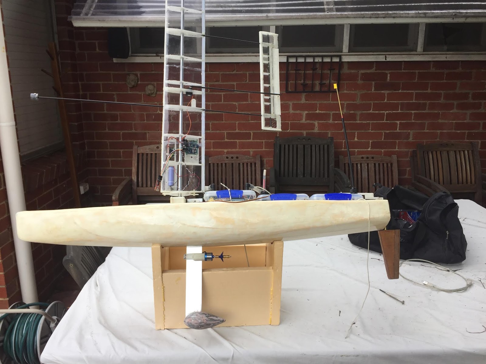
Voyager 2.0 Hull

Voyager 2.0 Hull


The hull was design using Freeship.
This is very powerful free hull design software.
The hull design was not intended to be sophisticated, just a simple balanced hull providing good buoyancy fore and aft.

Once the design was settled, lines were exported and transcribed on the 3mm marine ply to be used as stringers, glued between the closed cell construction foam.

The foam board used was available in 50mm sheets, 1200mm long. This was the main parameter for determining the hull dimensions for Voyager 2.0. 
Six pieces of foam were cut to shape to follow the lines from hull design.
They were all to be glued together with the plywood stringers in between using one part polyurethane glue.

It was found that the stringers were not needed, except for the central one incorporating the mast bearing tube and centreboard casing. The use of plywood stingers between the foam board would have made the hull far heavy than desired, and unnecessarily solid.


Screen shot of the hull lines in the Freeship program.


Central Plywood stringer part way through construction. It will incorporate the Centreboard Casing and Mast Bearing Tube
Closed Cell Foam Construction Board 1200mm long by 50mm thick


Shaped Hull being weighed, prior to Fibreglassing


The fibreglass cloth used was rated at 2 ounces.
Epoxy resin was used. (Polyester dissolves the foam. A lesson I stupidly learnt the hard way!)


Preparing to Layup the Fibreglass


First float test


Note: This is part of the ongoing development of a low cost autonomous oceangoing sailing drones, utilising a self-trimming wingsail. This is the Voyager series of sailing drones.